
Positioning system for industrial machine coupling elements

a technology of coupling elements and positioning systems, applied in the field of industrial machines, can solve the problems of shortening the installation cycle time, difficult alignment, and inconvenient operation,

Inactive Publication Date: 2017-08-31
GENERAL ELECTRIC CO
View PDF15 Cites 125 Cited by
  • Summary
  • Abstract
  • Description
  • Claims
  • Application Information

AI Technical Summary

Benefits of technology

The present disclosure aims to address certain problems and provide solutions.

Problems solved by technology

The extreme weight, size and varied mating shapes of the sections oftentimes makes alignment a very difficult task.
Currently, however, in certain situations, the fluid piping connections and other surroundings of the work environment are being installed prior to installation of the coupled turbomachine sections to, for example, shorten the installation cycle time.
Current techniques to position and align the sections rely on cranes, lifts and / or manual manipulation, all of which are imprecise and cumbersome.

Method used


Image

  • Positioning system for industrial machine coupling elements
  • Positioning system for industrial machine coupling elements
  • Positioning system for industrial machine coupling elements

Examples


Embodiment Construction

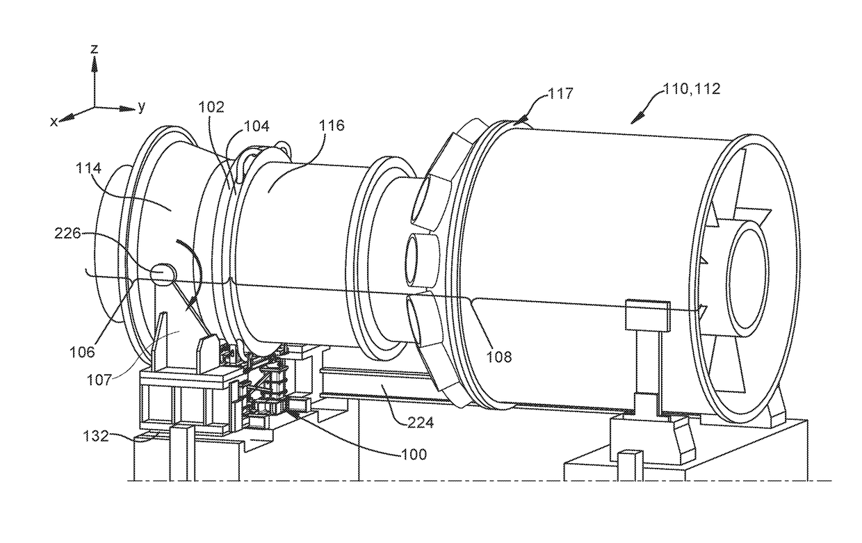
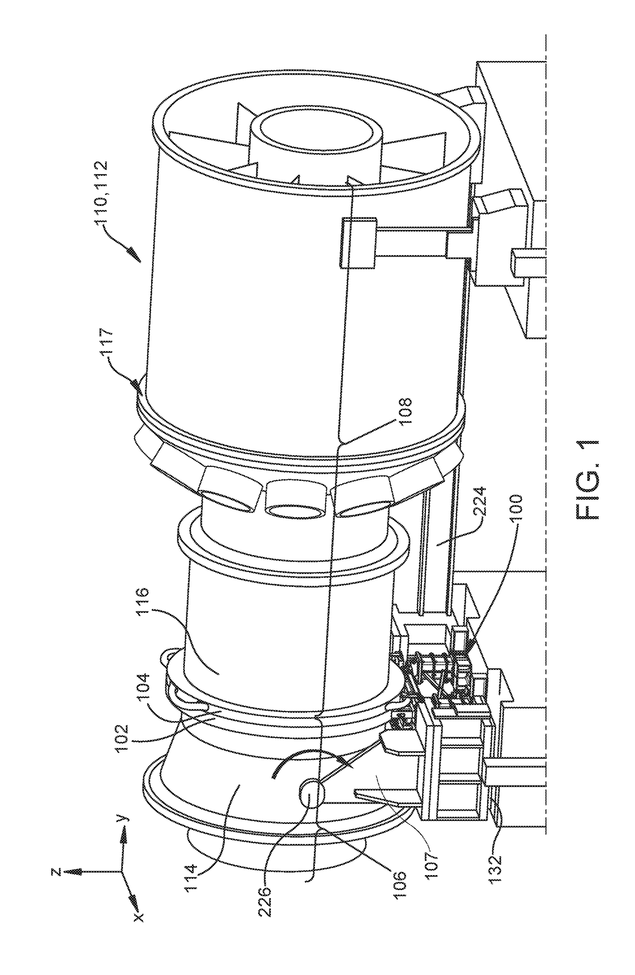
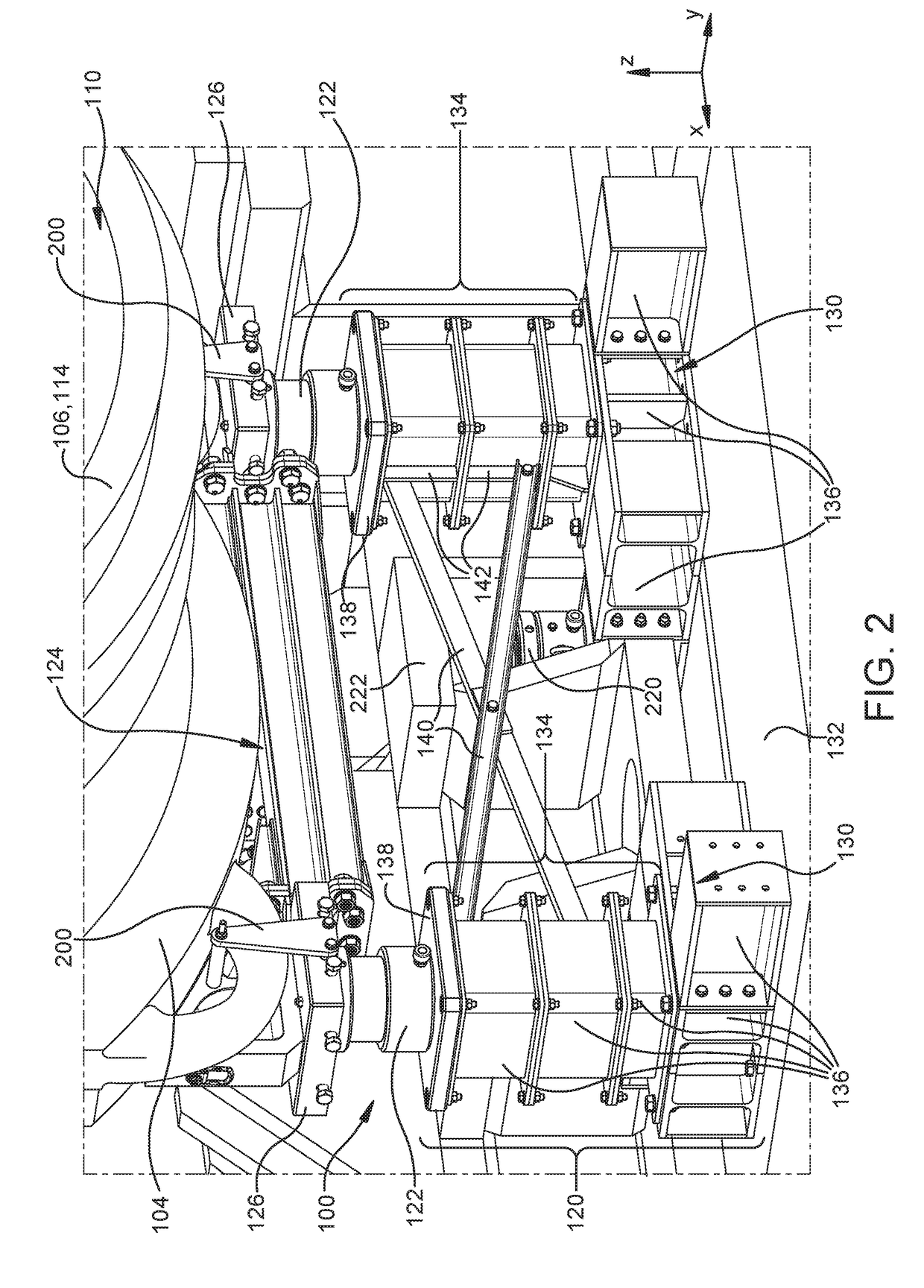
[0021]As indicated above, the disclosure provides a positioning system for precisely positioning and / or aligning first and second coupling elements of adjacent sections of an industrial machine. Embodiments of the disclosure will be described relative to an industrial machine in the form of a gas turbine power generating system that requires alignment of a rotating shaft of a gas turbine section thereof with the rotating shaft of an adjacent generator section thereof. In particular, the disclosure illustratively describes aligning a gas turbine inlet casing, and hence rotating shaft coupling element therein, with a compressor casing and hence the rotating shaft coupling element that extends therein which is coupled to, or part of, the rotating shaft of an adjacent generator section (not shown). In another setting, the teachings of the disclosure may be applied to aligning and coupling casing sections of a compressor. It is emphasized that embodiments of the disclosure can be applied...


PUM


Abstract

A positioning system for aligning first and second coupling elements of adjacent sections of an industrial machine such as a shaft of a turbomachine or generator is provided. The system may include a base, and a pair of lifting jacks supported by the base for adjusting a vertical position of the first coupling element relative to the second coupling element. A coupling element support supports the first coupling element and is supported by the pair of lifting jacks on the base. An adjusting element positioned between each lifting jack and the coupling element support allows adjusting a position of the first coupling element relative to the second coupling element in the axial direction and a lateral direction substantially perpendicular to the axial direction.

Description

BACKGROUND OF THE INVENTION[0001]The disclosure relates generally to industrial machines, and more particularly, to a positioning system for shaft alignment industrial machines such as a turbomachine and a generator.[0002]Large industrial machines oftentimes include a number of sections that must be positioned and coupled together in a precise, aligned fashion to ensure proper operation. The extreme weight, size and varied mating shapes of the sections oftentimes makes alignment a very difficult task. One illustrative class of industrial machines in which sections must be aligned includes turbomachines such as gas turbines, steam turbines, compressors, etc. In one example of the sections requiring alignment for a compressor, an inlet casing must be precisely aligned with the turbine casing of the compressor. In another example of the sections requiring alignment for a turbomachine, a rotating shaft of a gas turbine must be precisely aligned with the shaft of a generator.[0003]Conven...

Claims


Application Information

Patent Timeline
IPC IPC(8): F01D25/28F04D29/52F04D29/054F01D25/24
CPCF01D25/285F01D25/243F05D2240/60F04D29/054F05D2220/32F04D29/522F01D25/28F05D2230/64
Inventor DZIECIOL, PIOTR KRZYSZTOFO'MEARA, SEAN CORNELIUSPERKOWSKI, SZYMONWOJCIECHOWSKI, WIKTOR JAN
Owner GENERAL ELECTRIC CO
Learn More