Electromagnetic valve with spring tongues

Inactive Publication Date: 2017-08-31
ZF FRIEDRICHSHAFEN AG
View PDF16 Cites 1 Cited by
  • Summary
  • Abstract
  • Description
  • Claims
  • Application Information

AI Technical Summary

Benefits of technology

[0029]The valve seats of the valve openings can take on any desired suitable form, for example, circular or slit, with or without a spherical or conical depression. The closure assigned to one spring tongue can additionally be provided with a geometry corresponding to the valve seat to improve the sealing performance. In particular, the closure may be executed hemispherical or conical.
[0030]The suggested valve is characterized by a high dynamic, which is attributable to that it merely has low moving masses and no friction and a small formation of eddy currents due to the thin-walled elastic spring tongues. It is furthermore cost-efficient and realizable with few parts. Because of its high dynamic, it is resilient against active vibrations. Moreover, it does not tend to a seat bounce. It is low-wear a

Problems solved by technology

The drawback of this solution is that only a very small cross-section can be opened o

Method used


Image

  • Electromagnetic valve with spring tongues
  • Electromagnetic valve with spring tongues
  • Electromagnetic valve with spring tongues

Examples


Example

[0042]DETAILED DESCRIPTION OF THE DRAWINGS AND THE PRESENTLY PREFERRED EMBODIMENTS

[0043]In the figures, the same or at least similarly functional components / elements are provided with the same reference signs.

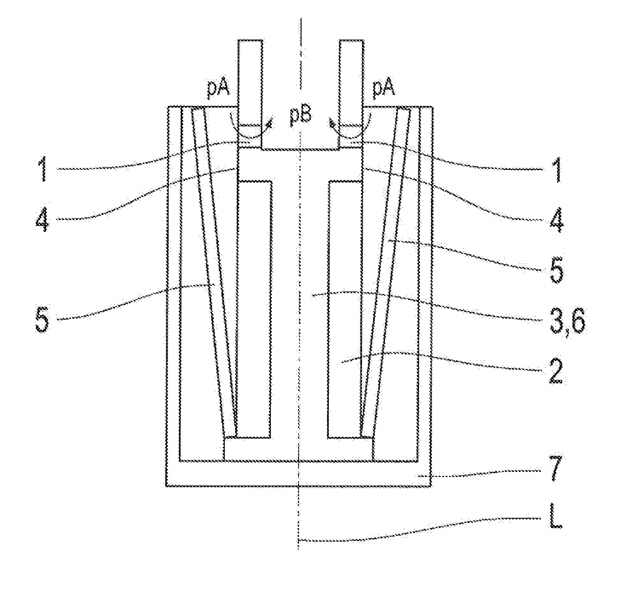
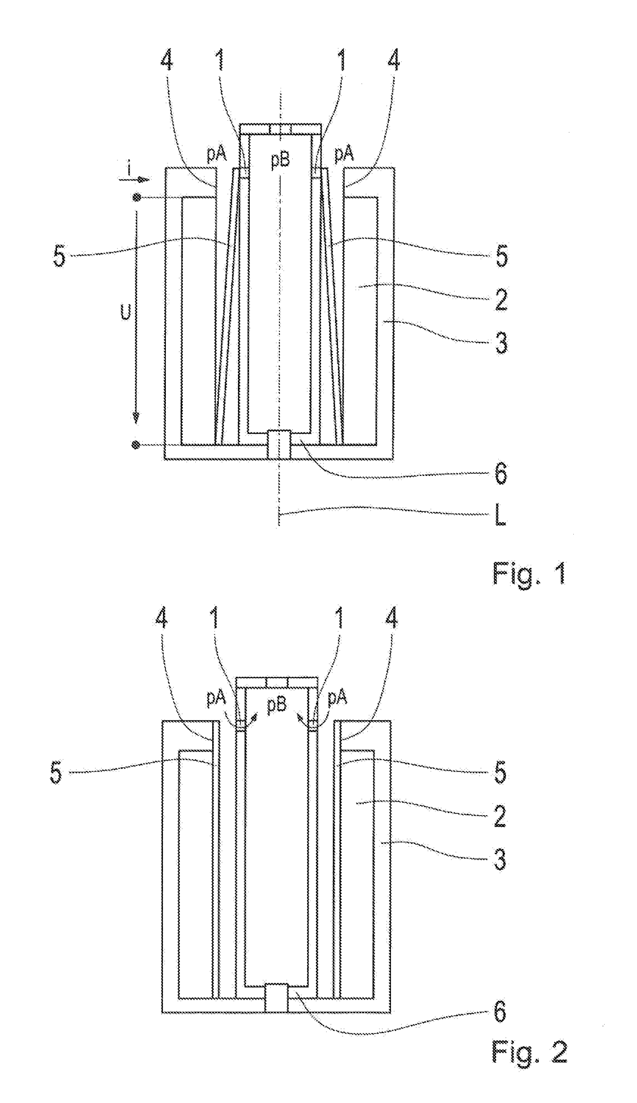
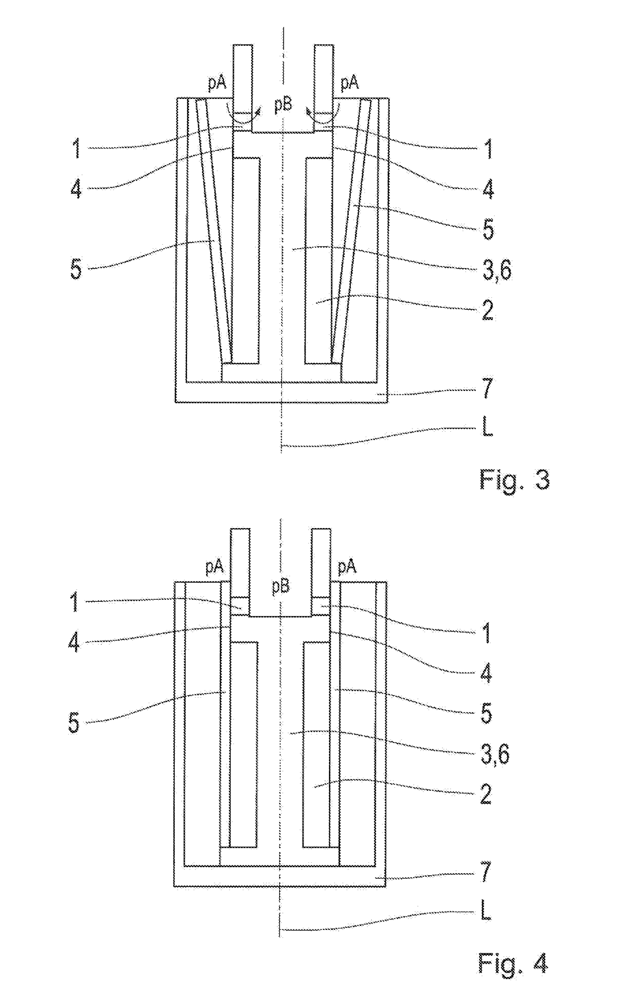
[0044]FIG. 1 shows an electrically operable valve by means of which a fluid flow can be enabled (valve opened) and prevented (valve closed). For this purpose, the valve has several first valve openings 1 by means of which the fluid can flow through the valve in the opened state. The valve furthermore comprises an electrical coil 2 that can be powered with an electrical current (voltage U, current I). Depending on the supplied current strength, a magnetic field forms in the area of the coil 2 in a familiar way.

[0045]The coil 2 is embedded in a magnet yoke 3. In the area of an axial front of the coil 2, the magnet yoke 3 has one or several pole shoes 4. The magnet yoke is intended to conduct the magnetic field as well as for the magnetic shielding of the surroundings of the coil...


PUM


Abstract

The invention relates to an electrically operable valve with an electrical coil and with several spring tongues, which are movable by means of a magnetic field generated by the coil between a first switch position and a second switch position each and with several first valve openings, which are opened when the spring tongues are in the first switch position and which are closed by means of the spring tongues when the spring tongues are in the second switch position.

Description

BACKGROUND[0001]1. Technical Field[0002]The invention relates to an electrically operable valve with at least one electric coil by means of which a locking element can be operated so that several valve openings of the valve can be closed and opened.[0003]2. Background Information[0004]Such a valve is known from DE 601 22 162 T2. Provision is hereby made for a spring tongue (linear anchor made from flat spring steel). The spring tongue is movable back and forth between two switch positions by means of an electric coil. In each of the two switch positions, the spring tongue closes a first valve opening and opens a second valve opening at the same time.[0005]The drawback of this solution is that only a very small cross-section can be opened or closed with the spring tongue by means of which a fluid can flow through the valve. It is therefore the task of the invention to provide for a valve that can release and close a larger flow cross-section.BRIEF SUMMARY[0006]This task is achieved t...

Claims


Application Information

Patent Timeline
IPC IPC(8): F16K31/06F16K31/08F16K11/10
CPCF16K31/0682F16K31/082F16K31/0624F16K11/10
Inventor KILTZ, LOTHARPANTKE, MICHAEL
Owner ZF FRIEDRICHSHAFEN AG
Why Eureka
Try Eureka