
Leak-proof tube fitting assembly structure

Active Publication Date: 2022-10-06
DONG GUAN HAN XU HARDWARE & PLASTIC TECH CO LTD
View PDF18 Cites 0 Cited by
  • Summary
  • Abstract
  • Description
  • Claims
  • Application Information

AI Technical Summary

Benefits of technology

The present invention is about a leak-proof tube fitting assembly structure that prevents leakage and ensures stability of the connection of the liquid tube and the liquid tube fitting, without falling off. It has a simple mechanism of a nut and three sealing members to achieve a double seal of the liquid tube and the liquid tube fitting. The operation is simple and convenient for assembly, and it is conducive to the later disassembly and maintenance, as well as playing a role in dust prevention. The invention has an ingenious and reasonable structure design, and it has the advantages of good leakage prevention, high assembly efficiency, and good assembly stability.

Problems solved by technology

Such a sealing structure has poor sealing performance and is prone to leakage.
However, the leak-proof performance is still not ideal, and it has disadvantages such as complex components and troublesome assembly.
It is not suitable for promotion and application.

Method used


Image

  • Leak-proof tube fitting assembly structure
  • Leak-proof tube fitting assembly structure
  • Leak-proof tube fitting assembly structure

Examples


first embodiment

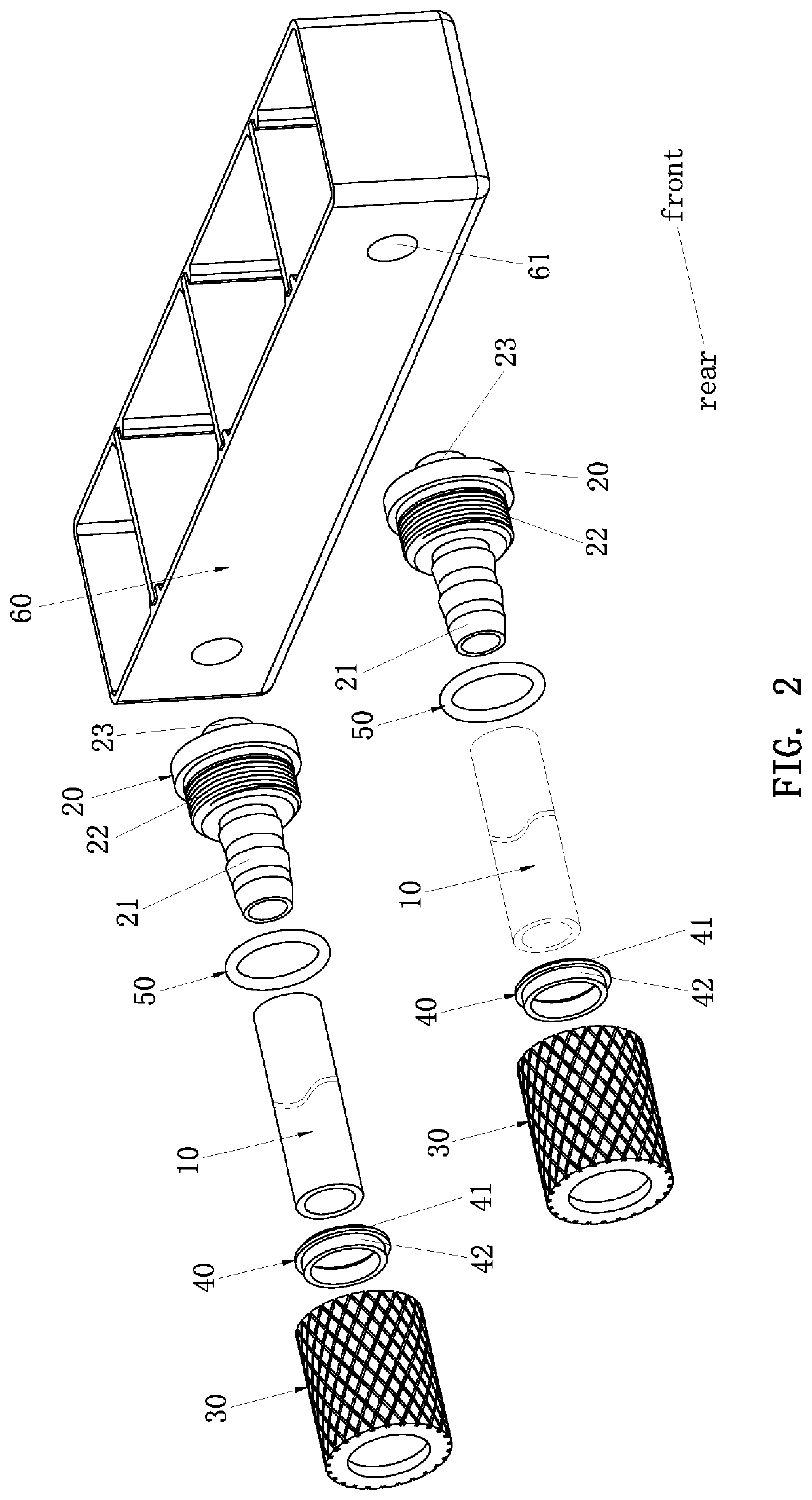
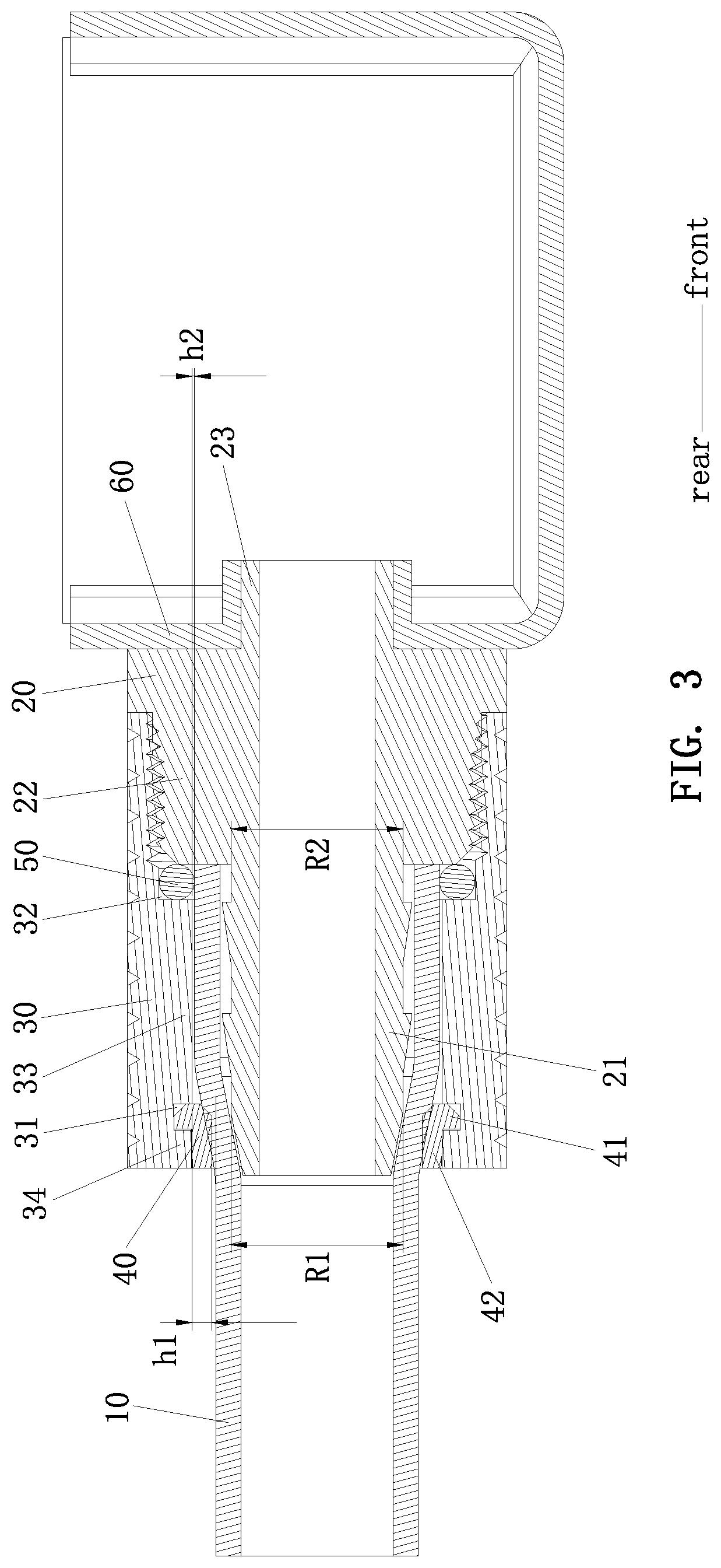
[0024]The second connecting end 23 of the liquid tube fitting 20 is connected to a reservoir 60. As shown in FIG. 3, in the first embodiment, the second connecting end 23 of the liquid tube fitting 20 is fixed in a mounting hole 61 of the reservoir 60 by welding.

second embodiment

[0025]As shown in FIG. 4, in the second embodiment, the second connecting end 23 of the liquid tube fitting 20 has a first dust-proof sealing face 24, an insert portion 25, a third positioning groove 26 and a second threaded connecting portion 27 that are axially arranged in sequence in the forward direction. The first dust-proof sealing face 24 is arranged corresponding to the periphery of the insert portion 25. The second threaded connecting portion 27 has a second external thread. The reservoir 60 has a mounting hole 61. The mounting hole 61 has a second dust-proof sealing face 62, a receiving hole portion 63 and an internal thread hole portion 64 that are axially arranged in sequence in the forward direction. The internal threaded hole portion 64 has a second internal thread. The inner diameter of the receiving hole portion 63 is greater than or equal to the maximum inner diameter of the internal thread hole portion 64. The receiving hole portion 63 and the internal thread hole ...


PUM


Abstract

A leak-proof tube fitting assembly structure includes a liquid tube, a liquid tube fitting, and a nut for locking and connecting the liquid tube and the liquid tube fitting. The liquid tube fitting has a first connecting end, a first threaded connecting portion and a second connecting end that are axially arranged in sequence in a forward direction. The first threaded connecting portion has a first external thread. Thereby, the sealing performance of the connection of the liquid tube and the liquid tube fitting is improved to prevent leakage.

Description

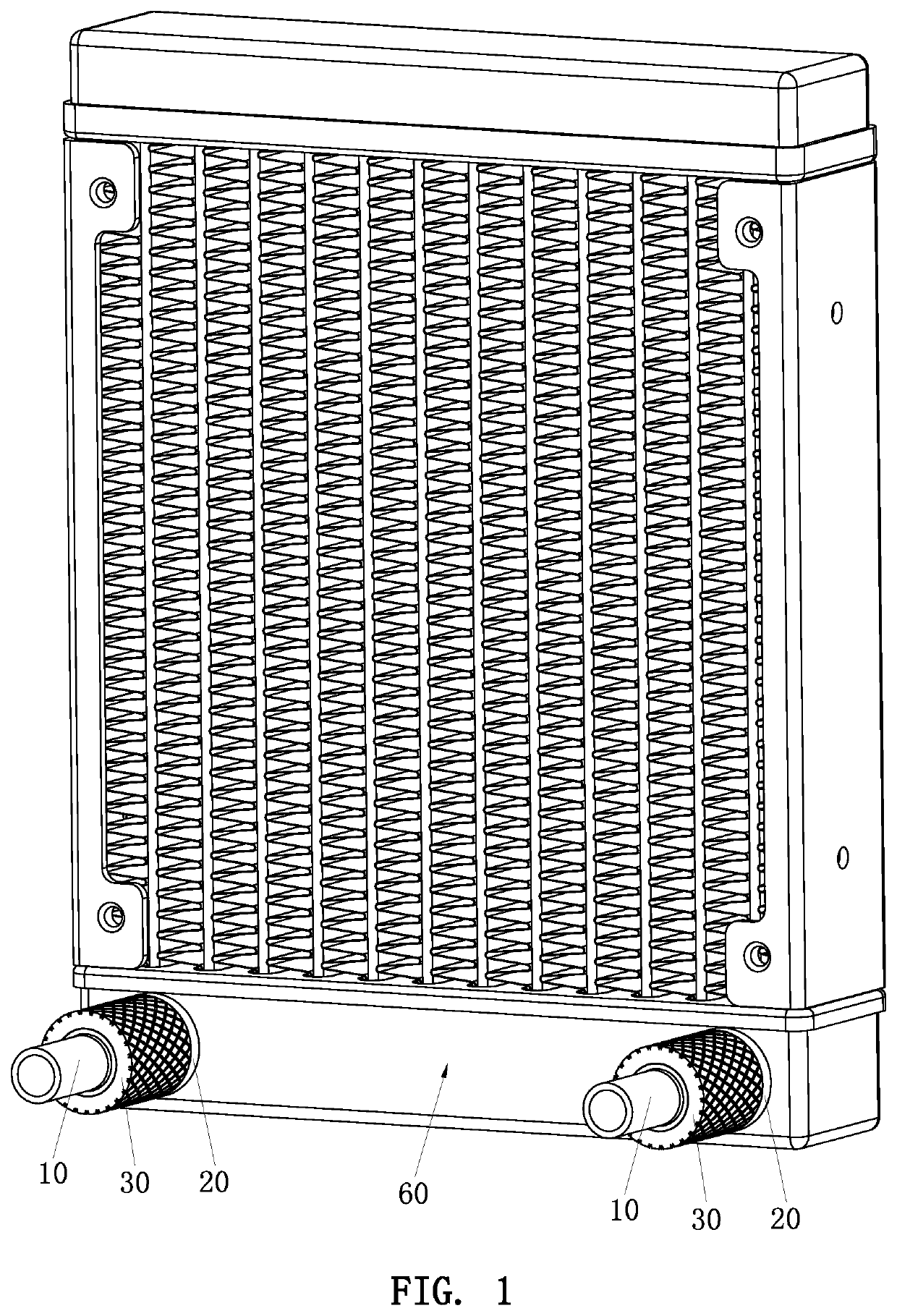
BACKGROUND OF THE INVENTION1. Field of the Invention[0001]The present invention relates to a tube fitting assembly structure, and more particularly to a leak-proof tube fitting assembly structure that is mainly applied to a liquid-cooling radiator, but not limited thereto.2. Description of the Prior Art[0002]A liquid-cooling radiator usually includes a cooling radiator and a liquid tube. The cooling radiator has a reservoir. The liquid tube is connected to the reservoir through a liquid tube fitting. The liquid tube and the liquid tube fitting are connected in a sleeve manner to achieve a sealing connection through the elastic deformation of the plastic of the liquid tube and the liquid tube fitting. Such a sealing structure has poor sealing performance and is prone to leakage. The liquid tube and the liquid tube fitting are easy to fall off. Later, a structure that uses a nut to lock the liquid tube and the liquid tube fitting is developed, which improves the leak-proof and anti-fa...

Claims


Application Information

Patent Timeline
IPC IPC(8): F16L19/04F16L19/065
CPCF16L19/043F16L19/065F16L19/0212F16L41/10F16L19/0283F16L19/041F16L19/046F16L33/223F16L33/225
Inventor HUANG, TSUNG-HSIEN
Owner DONG GUAN HAN XU HARDWARE & PLASTIC TECH CO LTD
Learn More