
Caliper brake

Pending Publication Date: 2022-11-10
HL MANDO CORP
View PDF0 Cites 0 Cited by
  • Summary
  • Abstract
  • Description
  • Claims
  • Application Information

AI Technical Summary

Benefits of technology

This patent describes a caliper brake that can improve its performance when braking is released, while also preventing drag and improving fuel efficiency in the vehicle. Additionally, it can prevent premature deformation of the seal member during low pressure braking, reducing the amount of braking fluid required and improving the driver's pedal feel. Finally, it can improve the rollback performance of the seal member without affecting assembly efficiency or shortening the assembly process time.

Problems solved by technology

However, in a conventional caliper brake, elastic deformation of the seal member is completed during a high pressure braking, but a slip in which a piston continuously advances is occurred.
Accordingly, the piston does not return smoothly when braking is released, resulting in occurring drag phenomenon in which the disk and the friction pads are rubbed.
However, in this case, due to increasing of a required amount of the braking fluid, when the brake pedal is operated an invalid stroke is increased and a pedal feel is reduced.

Method used


Image

  • Caliper brake
  • Caliper brake
  • Caliper brake

Examples


Embodiment Construction

[0035]Hereinafter, the embodiments of the disclosure will be described in detail with reference to accompanying drawings. It should be understood that the terms used in the specification and the appended claims should not be construed as limited to general and dictionary meanings, but interpreted based on the meanings and concepts corresponding to technical aspects of the disclosure on the basis of the principle that the inventor is allowed to define terms appropriately for the best explanation. Therefore, the description proposed herein is just a preferable example for the purpose of illustrations only, not intended to limit the scope of the disclosure, so it should be understood that other equivalents and modifications could be made thereto without departing from the spirit and scope of the disclosure.

[0036]Conventionally, a seal member 110 of a caliper brake is provided in a ring shape in which an outer circumferential surface 113 thereof is in close contact with an inner surface...


PUM


Abstract

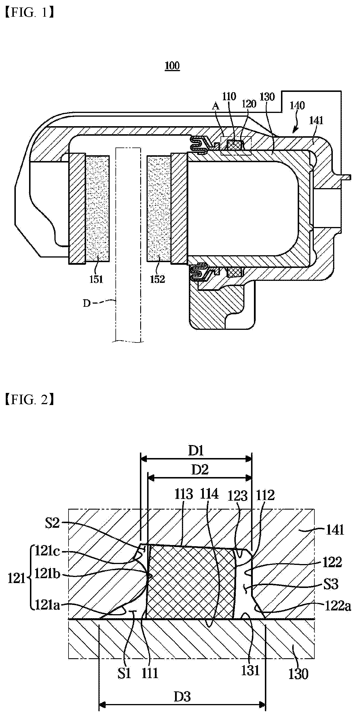
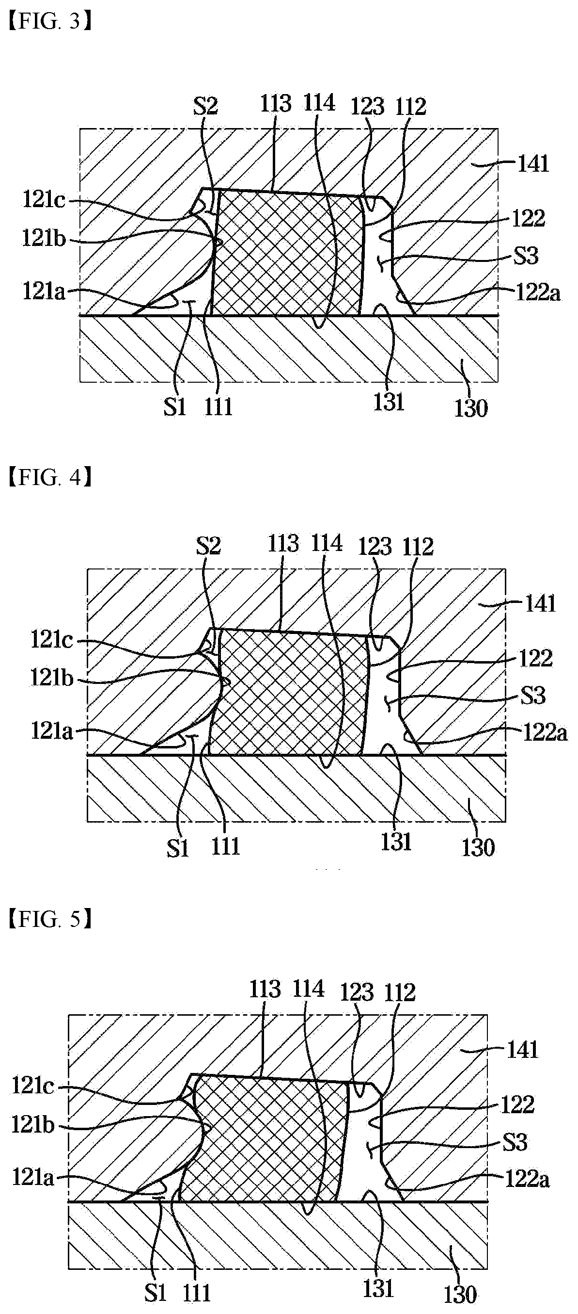
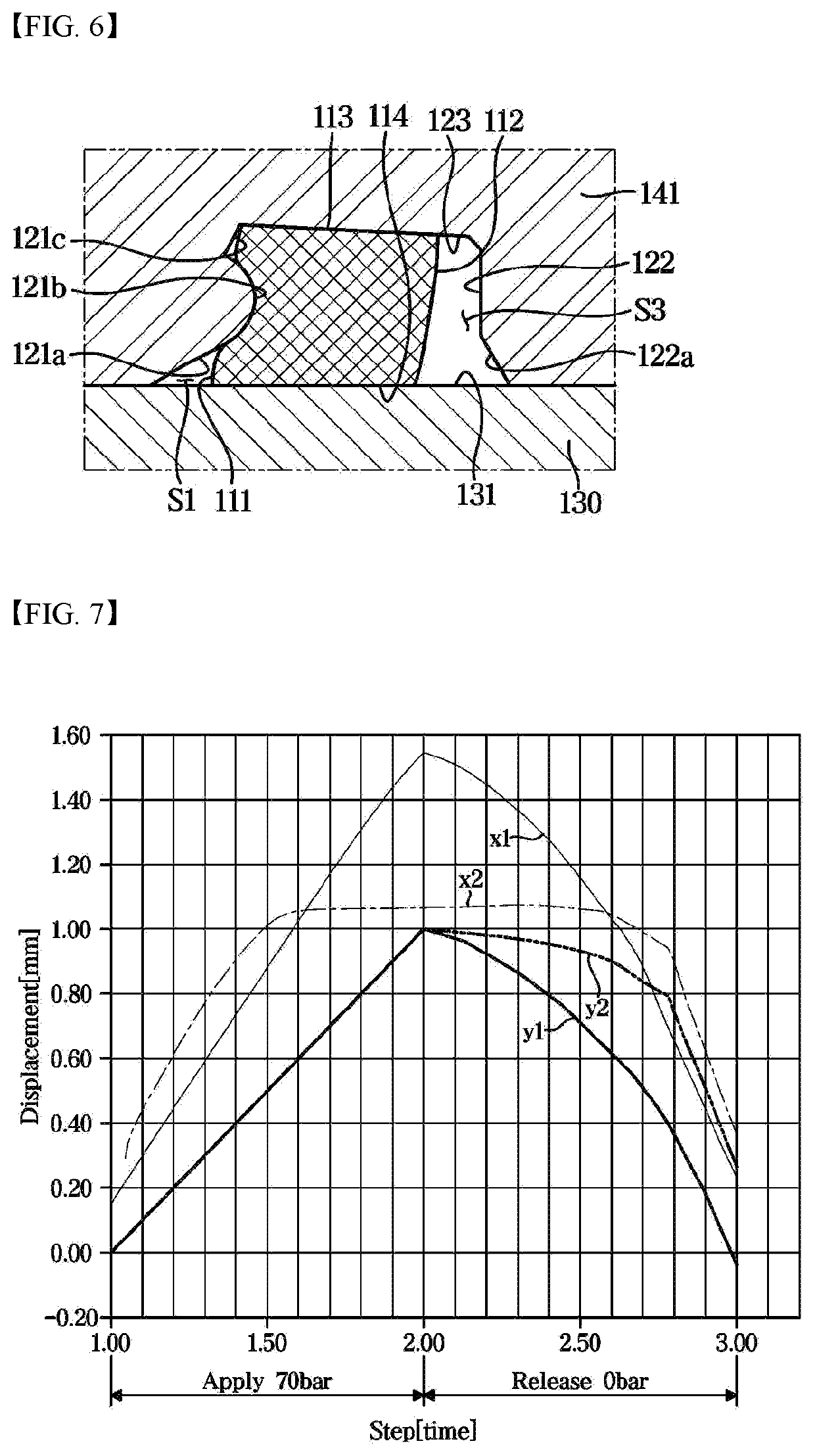
Disclosed herein a caliper brake includes a carrier in which a pair of pad plates are installed to move forward and backward toward a disk; a caliper housing slidably installed on the carrier and provided with a cylinder; a piston installed in the cylinder and configured to move forward and backward toward the pair of pad plates by a braking hydraulic pressure; a seal member in close contact with an outer surface of the piston and an inner surface of the cylinder, the seal member having a ring-shaped; and a seal groove formed to be recessed in the inner surface of the cylinder to accommodate the seal member, the seal groove including a front braking surface facing a front surface of the seal member; wherein the front braking surface includes a protrusion protruding toward the seal member.

Description

TECHNICAL FIELD[0001]The disclosure relates to a caliper brake, and more particularly, to a caliper brake including a seal member for rolling back a piston when braking is released.BACKGROUND ART[0002]In general, a caliper brake includes a disk rotating together with wheels of a vehicle, a carrier in which a pair of pad plates are installed to move forward and backward to press the disk, and a caliper housing slidably installed on the carrier. The caliper housing is provided with a cylinder in which a piston moves forward and backward by a braking hydraulic pressure.[0003]Such a caliper brake performs a service braking that pressurizes a piston by a braking hydraulic pressure, and also performs a parking brake that pressurizes the piston using a spindle unit that employs additionally an actuator operated by electricity to receive rotational force of a motor to convert a rotational motion into a linear motion. Generally, to reduce a drag phenomenon in which friction pads, that are at...

Claims


Application Information

Patent Timeline
IPC IPC(8): F16D55/226F16D65/18B60T11/236
CPCF16D55/226F16D65/183B60T11/236F16D2121/04F16D2125/08
Inventor KANG, DONG KOO
Owner HL MANDO CORP
Learn More