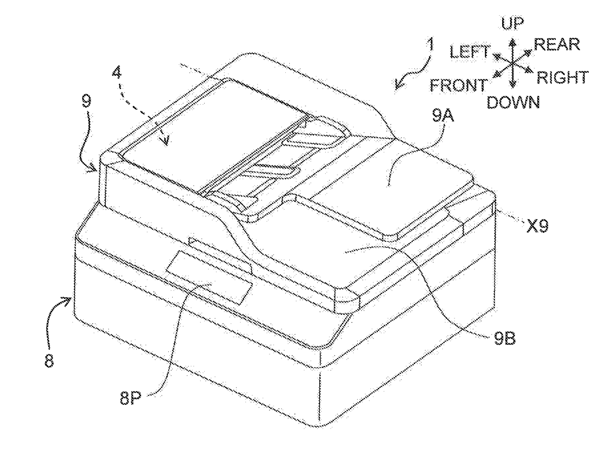
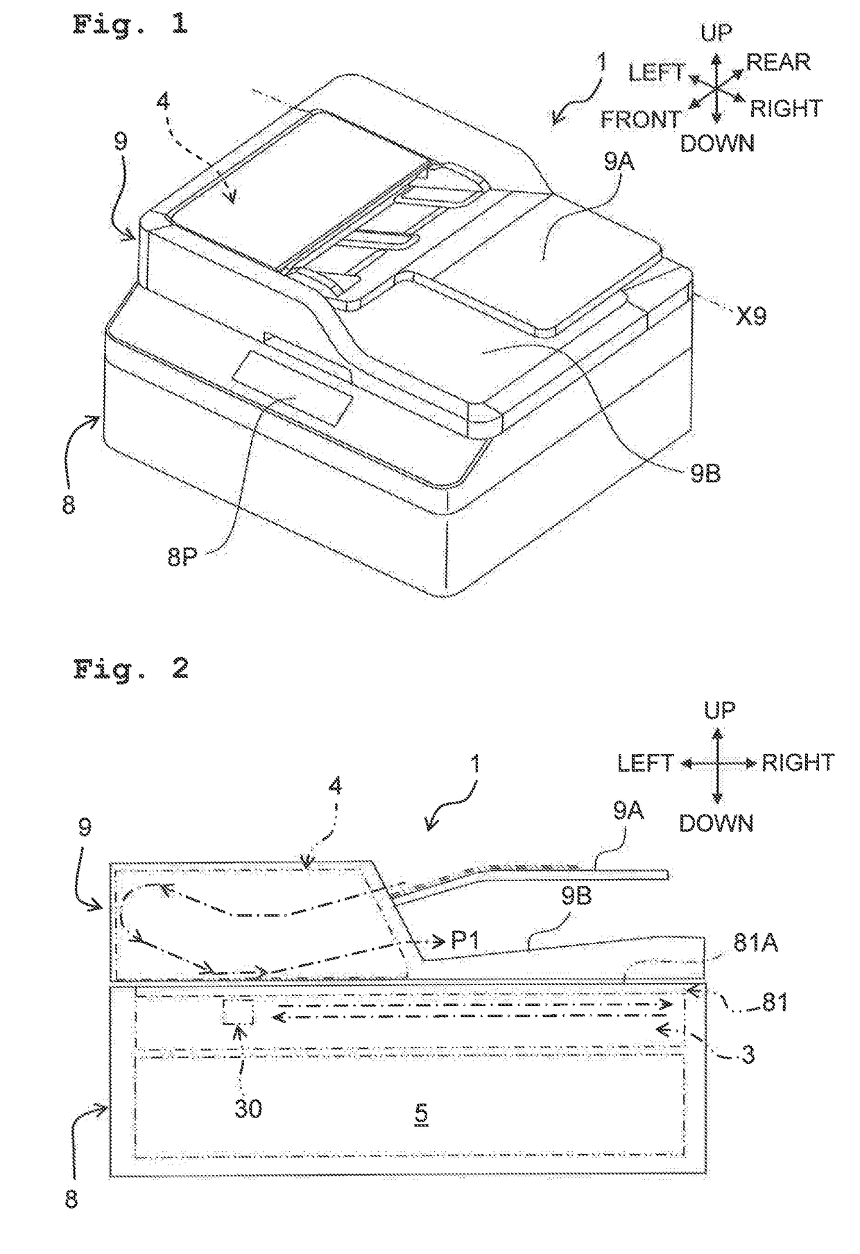
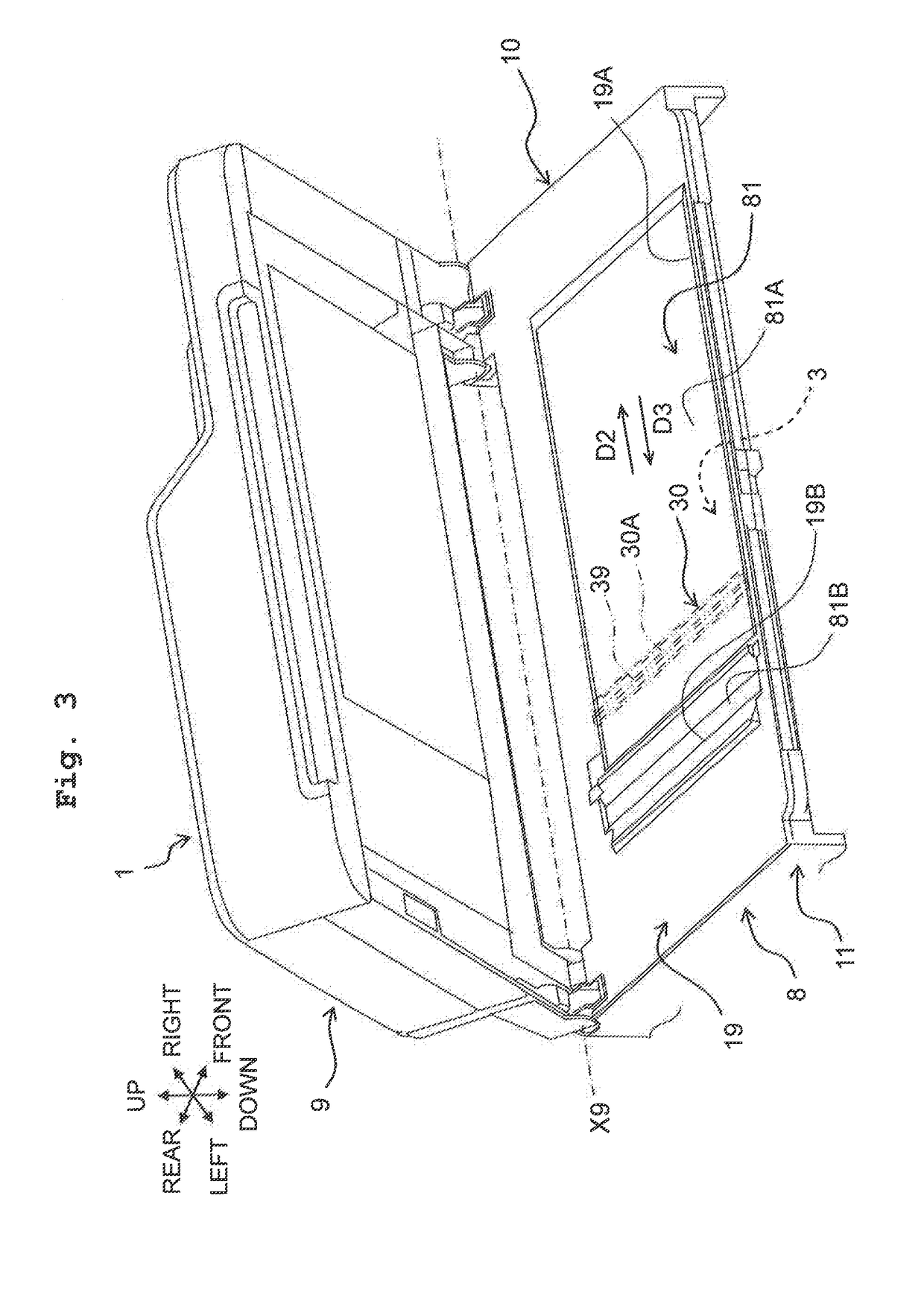
Image reading apparatus

a technology for reading apparatus and image, which is applied in the field of image reading apparatus, can solve the problems of difficult biasing force, low reading performance misalignment of each light-receiving element installed in the circuit board, and achieve the effect of simplifying the housing of line sensor unit, reducing manufacturing costs, and simplifying the back-surface wall of the housing covering the substra

Active Publication Date: 2017-08-31
BROTHER KOGYO KK
View PDF1 Cites 5 Cited by
  • Summary
  • Abstract
  • Description
  • Claims
  • Application Information

AI Technical Summary

Benefits of technology

[0007]Incidentally, in the image reading apparatus, it has been required to simplify the housing of the line sensor unit for miniaturization or lowering of manufacturing costs. In this respect, in the above-described conventional image reading apparatus, it is conceivable for a back-surface wall configuring the back surface of the housing in the line sensor unit to be thinned, the back-surface wall to be removed to expose the substrate, or the substrate to be covered by the likes of a sheet-like cover member. However, if the back-surface wall of the housing covering the substrate is simplified, it becomes easy for a biasing force of the coil spring to act on the substrate, and it becomes easy for the circuit board of the substrate to warp. As a result, in this image reading apparatus, there is a possibility that positioning of each of light-receiving elements installed in the circuit board is misaligned, and there is a possibility that reading performance of the line sensor unit lowers.
[0008]The present disclosure was made in view of the above-described conventional circumstances, and has an object of providing an image reading apparatus capable of achieving simplification of a reading section while suppressing a lowering of reading performance of the reading section.
[0028]The image reading apparatus of the present disclosure includes a transmission member which is of the above-described configuration. Another end of a first biasing section makes a contact with a connecting section of the transmission member, a first contacting section of the transmission member abuts in a first direction on an end at a position adjacent to a substrate section of a first wall, and a second contacting section of the transmission member abuts in the first direction on an end at a position adjacent to the substrate section of a second wall. As a result, a biasing force of the first biasing section is transmitted to a case. In this way, a reading section is biased toward a platen glass in a state that it is difficult for the biasing force of the first biasing section to act on the substrate section. Therefore, in this image reading apparatus, it becomes difficult for a circuit board of the substrate section to warp, even when simplification of a back surface configuration of the reading section is sought. As a result, misalignment of positioning of each of light-receiving elements installed in the circuit board can be suppressed.
[0029]Therefore, in the image reading apparatus of the present disclosure, simplification of the reading section can be achieved while a lowering of reading performance of the reading section is suppressed. Moreover, miniaturization or lowering of manufacturing costs of the image reading apparatus can be achieved.

Problems solved by technology

As a result, in this image reading apparatus, there is a possibility that positioning of each of light-receiving elements installed in the circuit board is misaligned, and there is a possibility that reading performance of the line sensor unit lowers.
In this way, a reading section is biased toward a platen glass in a state that it is difficult for the biasing force of the first biasing section to act on the substrate section.
Therefore, in this image reading apparatus, it becomes difficult for a circuit board of the substrate section to warp, even when simplification of a back surface configuration of the reading section is sought.

Method used


Image

  • Image reading apparatus
  • Image reading apparatus
  • Image reading apparatus

Examples


embodiment

Operational Effects of Embodiment

[0118]In the image reading apparatus 1 of the embodiment, as depicted in the likes of FIG. 13, the biasing member 70 is disposed at the front and rear in the housing space 10A. The upper end 71U of the coil spring portion 71 of the biasing member 70 abuts in the first direction D1 on the connecting portion 55 of the transmission member 50, the first contacting portion 51 of the transmission member 50 abuts in the first direction D1 on the lower end of the first wall 41, and the second contacting portion 52 of the transmission member 50 abuts in the first direction D1 on the lower end of the second wall 42. As a result, the biasing force F1 of the coil spring portion 71 of the biasing member 70 is transmitted to the case 40. Moreover, the biasing force F1 of the coil spring portion 71 is transmitted to the case 40 also by the third contacting portion53 of the transmission member 50 abutting in the first direction D1 on the lower end of the third wall ...


PUM


Abstract

An image reading apparatus is provided. The image reading apparatus includes: a platen glass; a moving member; a reading section held by the moving member, the reading section having a reading surface, a light-receiving element, a substrate section, and a case section; a transmission member; and a first biasing section. The moving member includes a facing surface that faces the substrate section. The case section includes a first wall and a second wall. The transmission member includes a first contacting section, a second contacting section, and a connecting section. The first biasing section is disposed such that its one end makes a contact with the facing surface of the moving member and its other end makes a contact with the connecting section of the transmission member.

Description

CROSS REFERENCE TO RELATED APPLICATION[0001]The present application claims priority from Japanese Patent Application No. 2016-034575, filed on Feb. 25, 2016, the disclosure of which is incorporated herein by reference in its entirety.BACKGROUNDField of the Invention[0002]The present invention relates to an image reading apparatus.Description of the Related Art[0003]Known as an example of a conventional image reading apparatus is an image reading apparatus that includes a platen glass, a guide member, a line sensor unit, and a coil spring. The platen glass supports a sheet by a front surface of the platen glass. The guide member is capable of reciprocating movement in a sub-scanning direction along a reverse surface of the platen glass, in a state of holding the line sensor unit. The line sensor unit has a reading surface and a plurality of optical sensor elements, and these elements are housed in a box-shaped housing. The reading surface includes a selfoc lens array and the like, an...

Claims


Application Information

Patent Timeline
Patent Type & Authority Applications(United States)
IPC IPC(8): H04N1/10H04N1/00
CPCH04N1/1061H04N1/1043H04N2201/0422H04N2201/0081H04N1/00519H04N1/04
Inventor KAWAMATA, NORIYUKI
Owner BROTHER KOGYO KK
Why Eureka
Try Eureka