Device for high-heeled shoes and method of constructing a high-heeled shoe

a high-heeled shoe and shoe technology, applied in the field of shoes, can solve the problems of introducing additional complexity and/or quality control issues in shoe manufacturing, affecting the comfort and stability of the shoe, and the reputation of conventional high-heeled shoes, so as to achieve smooth contouring and improve comfort and ankle stability. the effect of surprising and significant improvemen

Active Publication Date: 2017-09-07
HBN SHOE
View PDF15 Cites 8 Cited by
  • Summary
  • Abstract
  • Description
  • Claims
  • Application Information

AI Technical Summary

Benefits of technology

[0017]While high heel shoes in accordance with my aforesaid US '132, '346, '688 and '986 patents enjoy considerable commercial success and are available from a number of manufacturers in numerous countries, I have found that changing the shape of the heel region to better accommodate the plantar surface of the calcaneal tuberosity, comfort and ankle stability is unexpectedly and significantly improved. More particular, the present invention provides a device for insertion into high heel shoes and the corresponding method of constructing shoes using the device. The device comprises a rear region positioned to underlie the calcaneal tuberosity the wearer. The rear region is shaped to accommodate the plantar surface of the calcaneal tuberosities and includes first and second essentially ellipsoid shaped depressions to accommodate the calcaneal tuberosity of the wearer. The first depression, on the medial / inside of the device, i.e., under the medial tuberosity, is the larger of the two depressions, and is slightly deeper than the second depression on the lateral / outside of the device. Typically the depression on the medial / inside is 2-5 times larger than the depression on the lateral / outside preferably 2-4 times larger, more preferably 2½ -3 times larger, most preferably about 2¾ times larger in plan, than the depression on the lateral / outside of the device, i.e., under the lateral tuberosity, and the base level of the depression under the lateral tuberosity is slightly higher, e.g., about 1-3 mm higher, more preferably 1-2 nun higher, most preferably about ⅓ mm higher over the base level of the depression under the medial tuberosity to accommodate the calcaneal tuberosity of the wearer. The toeward portions of the first and second depressions gradually rise to crescent shaped apices lying under the area forward of the tuberosity of the calcaneus. The device also includes a forward region positioned to underlie at least a portion of the shafts of the metatarsals, the upper surface of said forward region having a portion which gradually rises to an apex positioned to underlie the shafts of the second and third metatarsals. In the preferred embodiment, the device has a bridging or middle region which connects the forward and rear regions, the device is flexible and the upper surface of the device is smoothly contoured between all regions. A feature and advantage of the device of the present invention is that the device may universally be applied to conventional high-heeled shoes without the need to otherwise modify the shoes or the shoe last. A shoe may be constructed with the device according to the present invention by incorporating the device into the shoe during the manufacturing process or the device may be applied post-manufacture by the wearer.

Problems solved by technology

Conventional high-heeled shoes have a reputation for being extremely uncomfortable.
This slight difference in calcaneal anatomy leads to ankle instability particularly for wearers of high heel shoes.
To be assured of a quality shoe construction, any such convexity and corresponding concavity must be carefully aligned during shoe manufacture, thereby introducing added complexity and / or quality control issues to shoe manufacture.
This results in pressure on the ball or forefoot regions and toe jamming which often gives rise to a burning sensation in these areas of the foot, as well as fatigue and discomfort in the foot and other areas of the body.
The prior art inserts and orthotics typically are relatively bulky and can affect a shoe's fit if added by the wearer after manufacture.

Method used


Image

  • Device for high-heeled shoes and method of constructing a high-heeled shoe
  • Device for high-heeled shoes and method of constructing a high-heeled shoe
  • Device for high-heeled shoes and method of constructing a high-heeled shoe

Examples


Embodiment Construction

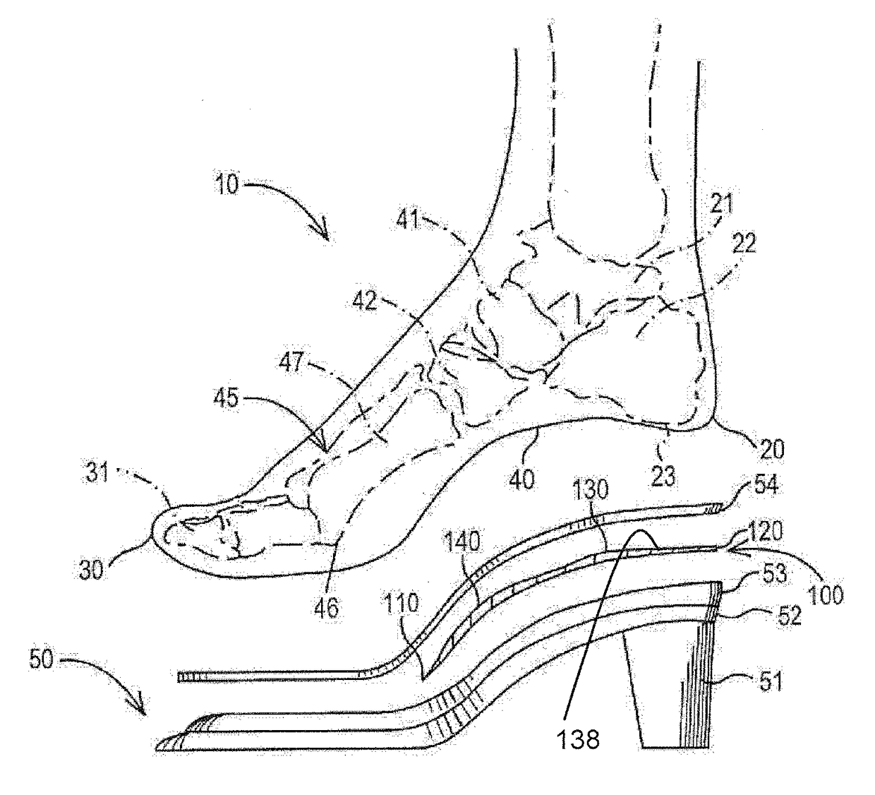
[0025]The present invention provides a device which improves comfort and is easily installed in high-heeled shoes. For purposes of this invention, it is to be understood that high-heeled shoes include all footwear having a heel which is about one inch or higher. The benefits of the invention are achieved when a device is positioned in a shoe to underlie the metatarsal shafts and calcaneus of the wearer. Typically, the device is positioned on the insole board or sock liner of a high-heeled shoe. Preferably, the device is sufficiently flexible so that it readily conforms to the upper surface of the insole board or sock liner on which it is positioned. The device may be formed of any materials known to those of ordinary skill in the art that can be molded or shaped and that will produce a device flexible under normal conditions of use of a shoe, while retaining sufficient dimensional stability to retain the benefit of the invention.

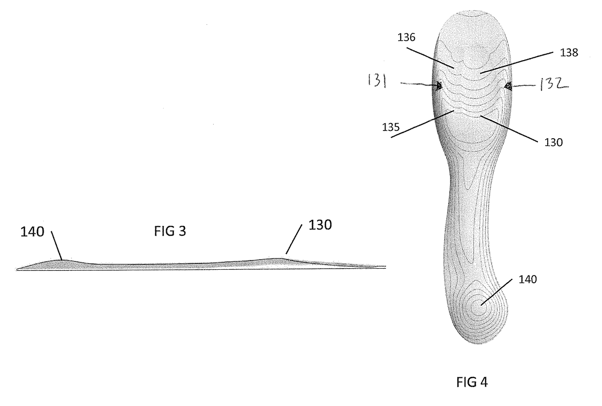
[0026]In the preferred embodiment, the device is shape...


PUM


Abstract

Provided is a device for insertion into a high heel shoe, having a rear region positioned to underlying a wearer's calcaneal tuberosity, the rear region being shaped to accommodate a planer surface of the wearer's calcaneal tuberosity, an upper surface of said rear region having a raised portion underlying an area of the wearer's calcaneus immediately forward of the wearer's calcaneus tuberosity; and a forward region positioned to underlie at least a portion of the shafts of the wearer's metatarsals, the second upper surface of said forward region having a raised portion which gradually rises to an apex position to underlie the shafts of the wearer's second and third metatarsals.

Description

BACKGROUND OF THE INVENTION[0001]The present invention relates to a shoe that is easily constructed and provides greater comfort to the wearer without affecting the fit or style of the shoe. The invention has particular utility in connection with high-heeled shoes.[0002]Conventional high-heeled shoes have a reputation for being extremely uncomfortable. There is survey information indicating that as many as 20% of the users of such shoes experience foot pain related to the shoes immediately, and the majority of users experience such pain after as little as four hours of use.[0003]In order to understand the prior art and the present invention, it is necessary to understand the anatomy of the foot and the basics of shoe construction. To that end, FIG. 1 is a diagrammatic view of the bones of the foot and the portions of a shoe that underlie the sole of the foot. By reference to FIG. 1, the following briefly describes the anatomy of the foot and the basics of shoe construction.[0004]FIG...

Claims


Application Information

Patent Timeline
Patent Type & Authority Applications(United States)
IPC IPC(8): A43B7/14A43B17/02
CPCA43B7/141A43B17/02A43B7/148A43B7/1445A43B7/144
Inventor HUGHES, BRIAN G. R.DANANBERG, HOWARD
Owner HBN SHOE
Why Eureka
Try Eureka