Portable foldable supporting assembly

Inactive Publication Date: 2017-09-07
WU YAO CHUAN
View PDF0 Cites 6 Cited by
  • Summary
  • Abstract
  • Description
  • Claims
  • Application Information

AI Technical Summary

Benefits of technology

[0005]The main objective of the invention is to provide a supporting device that is por

Problems solved by technology

However, in some public places, such as stations, airports or hospitals, no facilities are provided to allow users to operate portal devices in these public places.
Therefore the portable device is usually put on the lap of the user for operation, but this will cause inco

Method used


Image

  • Portable foldable supporting assembly
  • Portable foldable supporting assembly
  • Portable foldable supporting assembly

Examples


Embodiment Construction

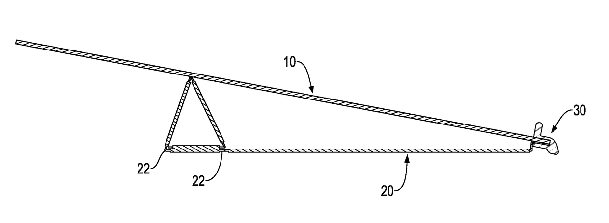
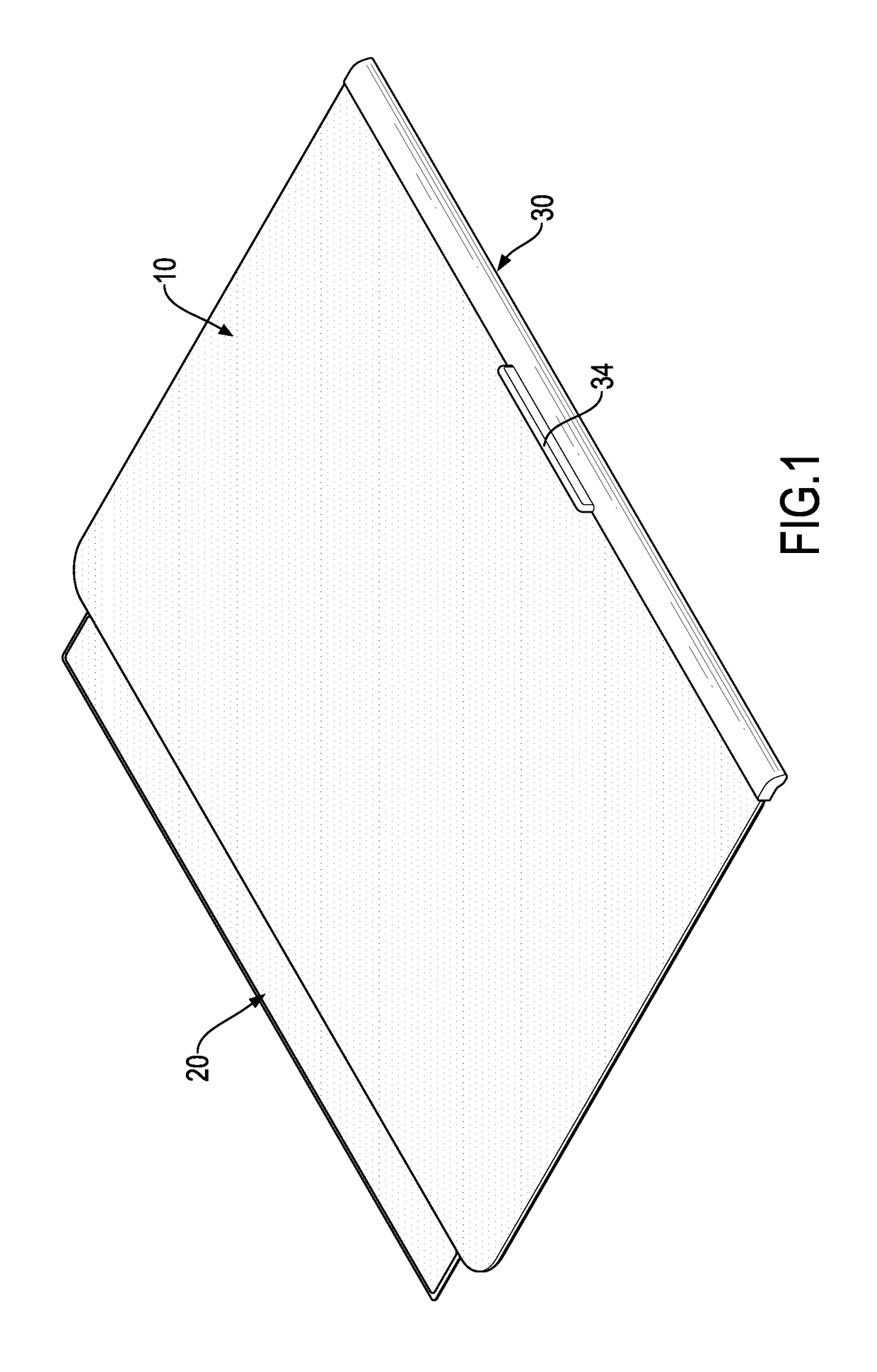
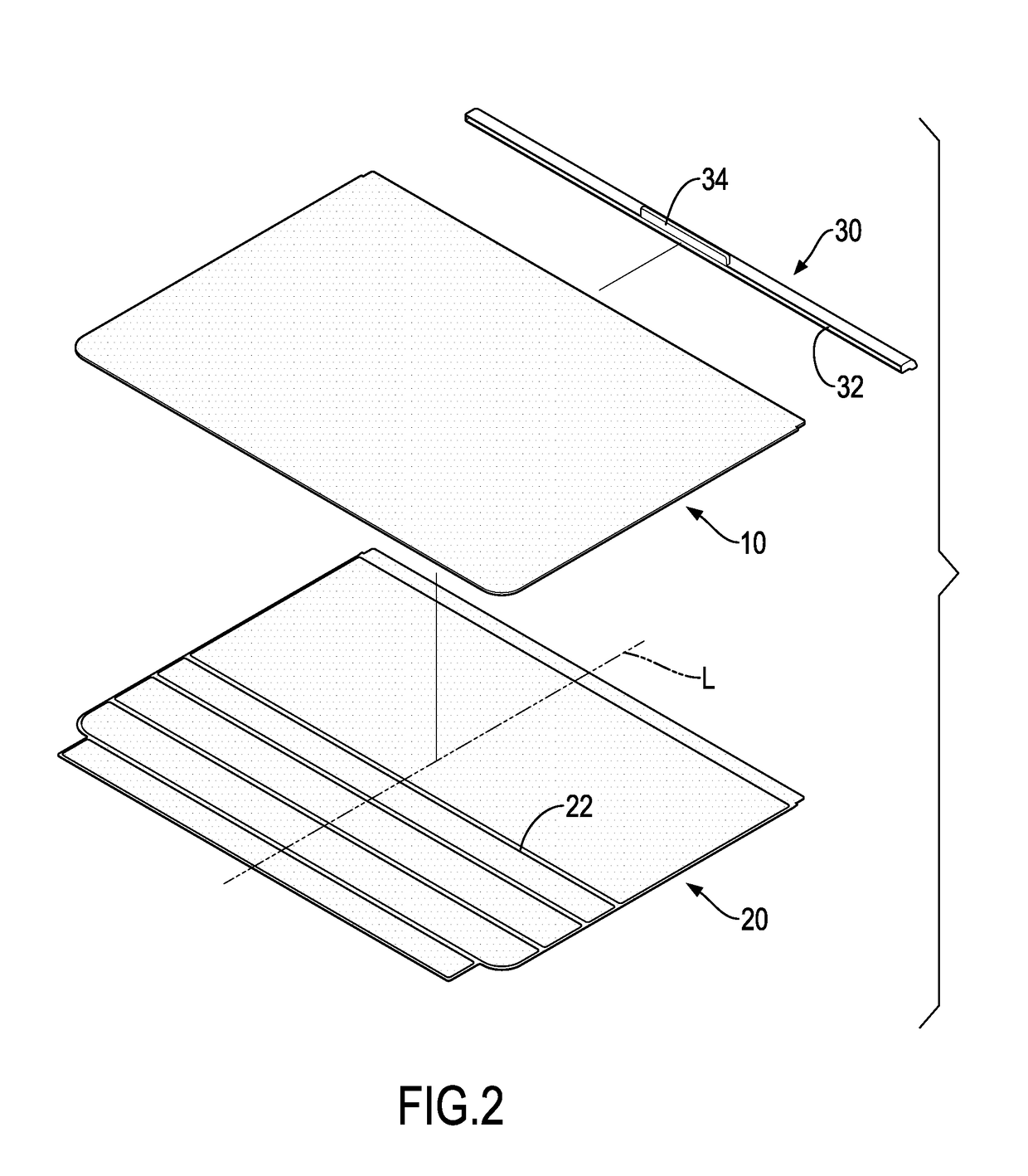
[0014]With reference to FIGS. 1 to 3, a supporting assembly in accordance with the present invention comprises a supporting board 10 and a baseboard 20. The supporting board 10 may be a quadrilateral board. The baseboard 20 is connected to and located below the supporting board 10 and has a connection end and a folding end. The connection end is connected to the supporting board 10 to allow the supporting board 10 to pivot relative to the baseboard 20. To connect the supporting board 10 with the baseboard 20, a clamping bar 30 is provided. The clamping bar 30 has an insertion slot 32 defined in the clamping bar 30. The connection end of the baseboard 20 and an edge of the supporting board 10 are inserted into the insertion slot 32 and are clamped by the clamping bar 30 to connect the supporting board 10 with the baseboard 20 by the clamping bar 30. In addition, the clamping bar 30 further has a supporting block 34 formed on and protruding from the clamping bar 30.

[0015]The folding e...


PUM


Abstract

A supporting assembly has a supporting board and a baseboard. The baseboard is connected to and located below the supporting board and has a connection end and a folding end. The connection end is connected to the supporting board to allow the supporting board to pivot relative to the baseboard. The folding end is opposite the connection end and has multiple folding segments formed on the folding end.

Description

BACKGROUND OF THE INVENTION[0001]1. Field of the Invention[0002]The present invention relates to a supporting assembly, and more particularly to a supporting assembly that is portable and foldable.[0003]2. Description of Related Art[0004]A portable device, such as a notebook computer or a tablet computer is popular due to the small volume, light weight, and convenience of use thereof. However, in some public places, such as stations, airports or hospitals, no facilities are provided to allow users to operate portal devices in these public places. Therefore the portable device is usually put on the lap of the user for operation, but this will cause inconvenience of using the portable device. In addition, when the portal device is used in an office, the portable device is put on an office desk. To adjust angle of the screen of the portable device, such as a notebook computer, the screen is pivoted relative to a main body of the computer. However, the pivotal rotation of the screen eas...

Claims


Application Information

Patent Timeline
IPC IPC(8): F16M11/38A47B23/00
CPCA47B23/001F16M11/38A47B23/044F16M11/10F16M13/00F16M2200/08
Inventor WU, YAO CHUAN
Owner WU YAO CHUAN
Why Eureka
Try Eureka