Electricity storage system and control method of electricity storage system

a technology of electricity storage system and control method, which is applied in the direction of electrochemical generators, secondary cell servicing/maintenance, transportation and packaging, etc., can solve the problems that the control of multiple storage battery units cannot be achieved by cell balancing or module balancing

Active Publication Date: 2017-09-14
PANASONIC INTELLECTUAL PROPERTY MANAGEMENT CO LTD
View PDF3 Cites 32 Cited by
  • Summary
  • Abstract
  • Description
  • Claims
  • Application Information

AI Technical Summary

Benefits of technology

[0007]According to the electricity storage system according to an embodiment of the present disclosure, multiple storage battery units can be appropriately controlled.

Problems solved by technology

However, there are cases where cell balancing or module balancing is not appropriate for control of multiple storage battery units.

Method used


Image

  • Electricity storage system and control method of electricity storage system
  • Electricity storage system and control method of electricity storage system
  • Electricity storage system and control method of electricity storage system

Examples


first embodiment

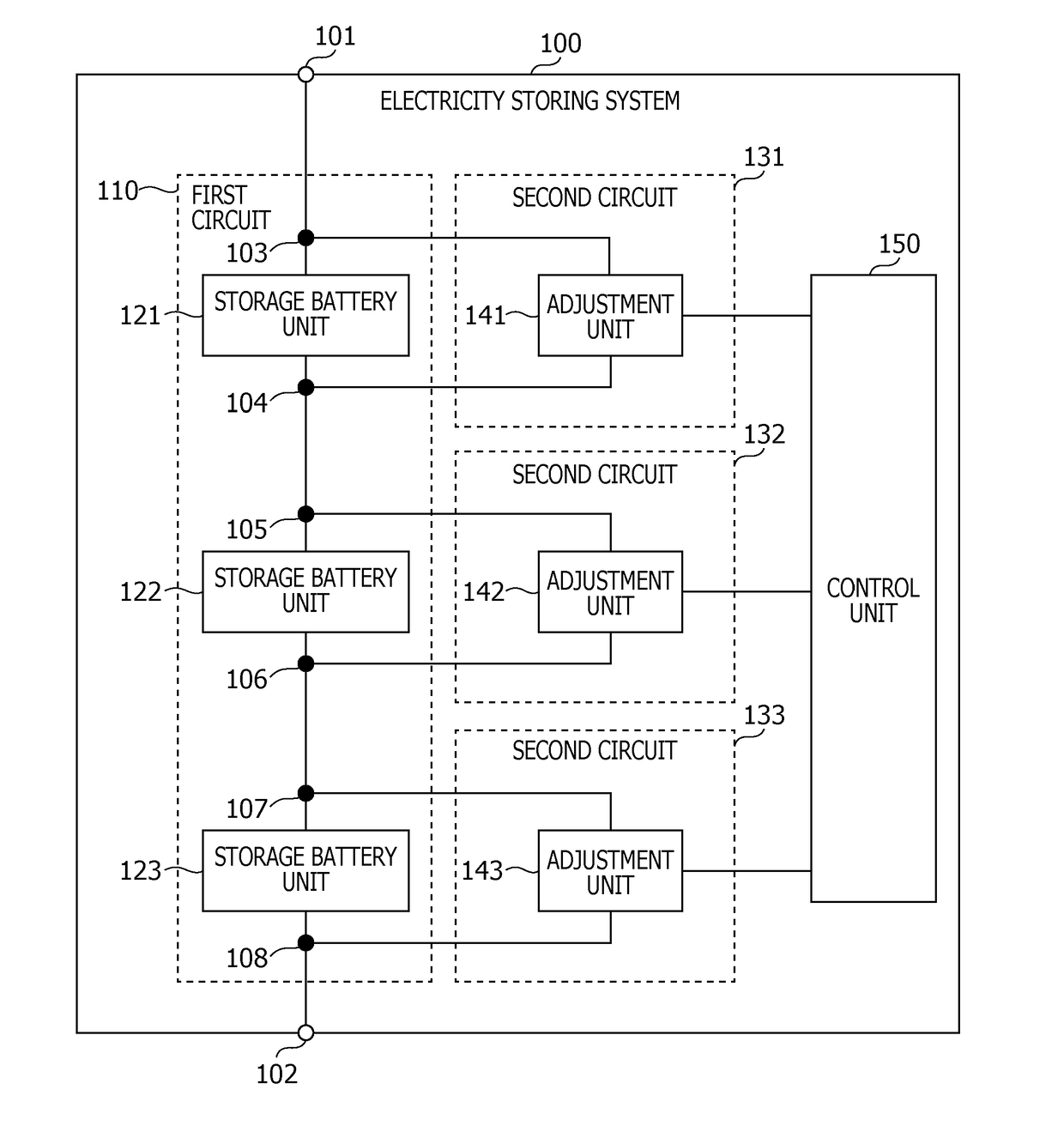
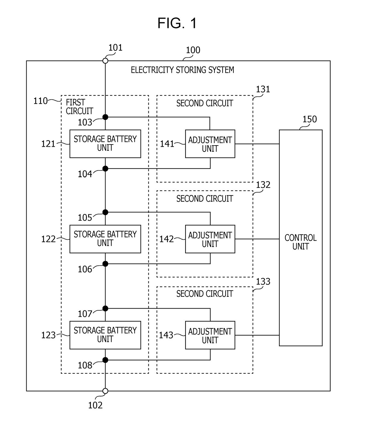
[0078]FIG. 1 is a block diagram illustrating the configuration of an electricity storage system according to a first embodiment. The charging system 100 illustrated in FIG. 1 controls storage battery units 121, 122, and 123. The electricity storage system 100 may be configured as a single device or as multiple devices. The electricity storage system 100 also includes a first circuit 110, second circuits 131, 132, and 133, and a control unit 150.

[0079]The first circuit 110 is an example of a first circuit according to the present disclosure, and is an electric circuit where the storage battery units 121, 122, and 123 are serially connected. The first circuit 110 corresponds to a path from a terminal 101 of the electricity storage system 100 through the storage battery units 121, 122, and 123 and reaching a terminal 102 of the electricity storage system 100. One of the terminal 101 and terminal 102 is a positive terminal for electric power, and the other is a negative terminal for ele...

second embodiment

[0111]A second embodiment corresponds to a specific example of the first embodiment. Part of the configuration and part of the operations shown in the present embodiment may be combined with the configuration and operations shown in the first embodiment.

[0112]FIG. 4 is a block diagram illustrating the configuration of the electricity storage device 200 according to the present embodiment. The heavy lines in FIG. 4 represent paths for transporting electric power, while the light lines and dotted lines between the components represent paths for conveying information. Multiple paths may be provided between the components for transmitting information, as indicated in FIG. 4. These paths may differ depending on the type of information, or may differ depending on the direction of transmission.

[0113]The electricity storage device 200 illustrated in FIG. 4 includes storage battery modules 211, 212, and 213, adjusters 261, 262, and 263, a communication unit 270, a control unit 280, and a pow...


PUM


Abstract

An system includes: a first circuit that serially connect storage battery units; second circuits; adjusters that adjust an amount of current flowing at the second circuits; and a controller that executes at least one of first control where voltage at a first storage battery unit is made to be higher than voltage at a second storage battery unit regarding which prediction has been made that a degree of deterioration will be greater than the degree of deterioration of the first storage battery unit, and charging is stopped, and second control where the adjusters are controlled and voltage at the first storage battery unit is made to be lower than voltage at the second storage battery unit, and discharging is stopped.

Description

BACKGROUND[0001]1. Technical Field[0002]The present disclosure relates to an electricity storage system and the like that controls multiple storage battery units.[0003]2. Description of the Related Art[0004]Japanese Unexamined Patent Application Publication No. 2014-096918 is a technology relating to an electricity storage system where multiple storage cells are controlled. The control device is described in Japanese Unexamined Patent Application Publication No. 2014-096918 as performing cell balancing or module balancing. However, there are cases where cell balancing or module balancing is not appropriate for control of multiple storage battery units.SUMMARY[0005]One non-limiting and exemplary embodiment provides an electricity storage system capable of appropriately controlling multiple storage battery units.[0006]In one general aspect, the techniques disclosed here feature a system including: a first circuit that serially connect storage battery units; second circuits that are co...

Claims


Application Information

Patent Timeline
Patent Type & Authority Applications(United States)
IPC IPC(8): H02J7/00
CPCH02J7/0021H02J7/0016H01M10/4207H01M10/425H01M10/441H01M2010/4271H02J7/005H02J7/0013H02J7/0049Y02E60/10
Inventor TOYA, SHOICHI
Owner PANASONIC INTELLECTUAL PROPERTY MANAGEMENT CO LTD
Why Eureka
Try Eureka