Counterweight for elevator system

Active Publication Date: 2017-10-05
OTIS ELEVATOR CO
View PDF8 Cites 0 Cited by
  • Summary
  • Abstract
  • Description
  • Claims
  • Application Information

AI Technical Summary

Problems solved by technology

However, older elevator systems may have an asymmetrical layout, where the counterweight is not generally centered relative to

Method used


Image

  • Counterweight for elevator system
  • Counterweight for elevator system
  • Counterweight for elevator system

Examples


Example

[0031]The detailed description explains embodiments of the invention, together with advantages and features, by way of example with reference to the drawings.

DETAILED DESCRIPTION OF THE INVENTION

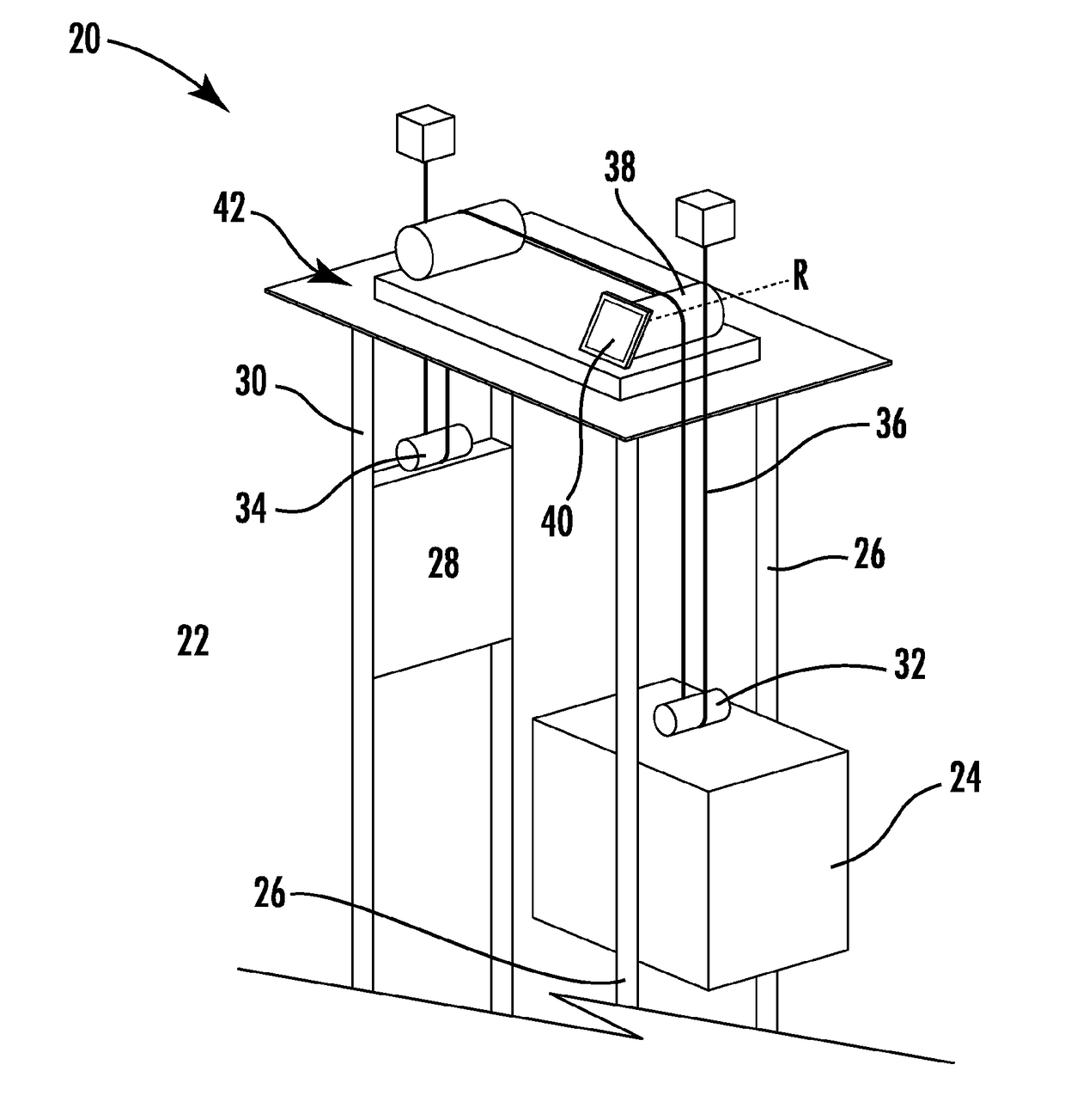
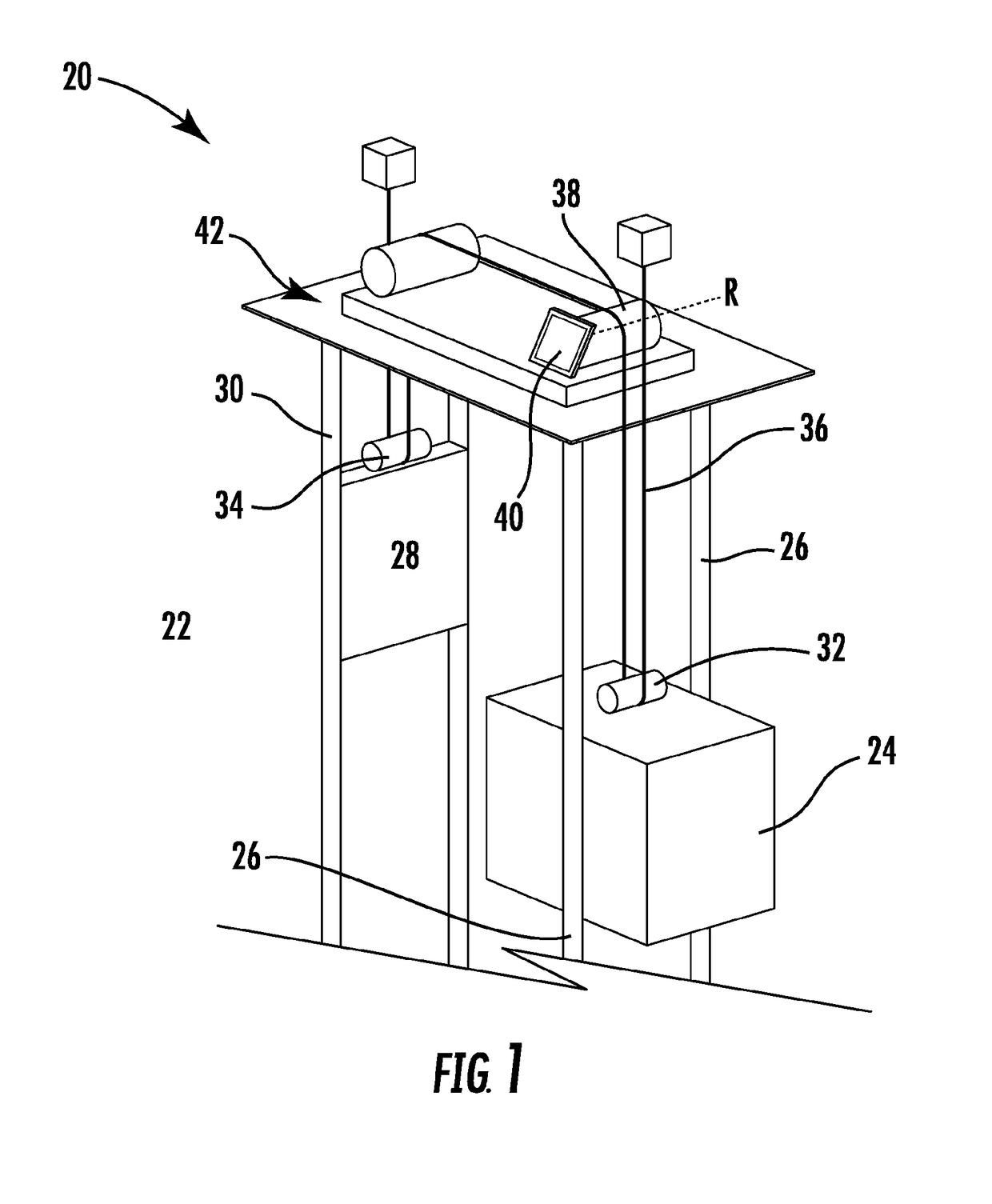
[0032]Referring now to FIG. 1, an exemplary elevator system 20 is illustrated. The elevator system 20 includes an elevator car 24 configured to move vertically upwardly and downwardly within a hoistway 22 along a plurality of car guide rails 26. Guide assemblies mounted to the top and bottom of the elevator car 24 are configured to engage the car guide rails 26 to maintain proper alignment of the elevator car 24 as it moves within the hoistway 22.

[0033]The elevator system 20 also includes a counterweight 28 configured to move vertically upwardly and downwardly within the hoistway 22. The counterweight 28 moves in a direction generally opposite the movement of the elevator car 24 as is known in conventional elevator systems. Movement of the counterweight 28 is guided by counterweight guide ra...


PUM


Abstract

A counterweight is provided including a counterweight frame including a crosshead. A counterweight hitch is operably coupled to the counterweight frame. The counterweight hitch includes a vertically stacked first sheave channel and a second sheave channel. Each of the first sheave channel and second sheave channel includes an interior cavity within which at least one individual sheave assembly is mounted. The plurality of individual sheave assemblies is substantially identical and arranged at an angle relative to a central plane of the counterweight frame.

Description

CROSS-REFERENCE TO RELATED APPLICATIONS[0001]This application claims the benefit of U.S. provisional patent application Ser. No. 62 / 043,133 filed Aug. 28, 2014, the entire contents of which are incorporated herein by reference.BACKGROUND OF THE INVENTION[0002]Embodiments of the invention relate to elevator systems, and more particularly, to an elevator system having an asymmetric counterweight.[0003]Vertical travel of an elevator car is typically powered by a drive assembly that may be supported within an upper portion of an elevator hoistway by a support member, such as a bedplate for example. The drive assembly generally includes a traction machine composed of a gearless motor and a traction sheave, both of which may be mounted on a surface of the bedplate. Rotational torque generated by the motor is used to drive the traction sheave. Depending on the direction of rotation of the motor the traction sheave causes tension members to lift or lower the elevator car and counterweight v...

Claims


Application Information

Patent Timeline
IPC IPC(8): B66B17/12B66B9/00
CPCB66B9/00B66B17/12B66B7/085
Inventor ST. PIERRE, BRUCEDAVIS, III, DANIEL B.SWAYBILL, BRUCE P.
Owner OTIS ELEVATOR CO
Why Eureka
Try Eureka