

Flow straightener and mixer
a technology of flow straightener and mixer, which is applied in the direction of machines/engines, combustion types, lighting and heating apparatus, etc., can solve the problems of high nox emission level and higher life cycle cos
Active Publication Date: 2015-01-27
ANSALDO ENERGIA SWITZERLAND AG
View PDF16 Cites 32 Cited by
- Summary
- Abstract
- Description
- Claims
- Application Information
AI Technical Summary
Problems solved by technology
As a result, there can arise high NOx emission levels and higher life cycle costs.
This criterion can pose challenges in obtaining appropriate distribution of the fuel across the burner exit area.
Method used
View moreImage
Smart ImageViewing Examples

Examples
embodiment 1
[0151]Staggering of lobes to eliminate vortex-vortex interactions. The vortex-vortex interactions result in not effectively mixing the fuel air streams.
embodiment 2
[0152]Careful placement and location of fuel injection on the lobes: Fuel jets can be placed in the areas of high shear regions in order to best utilize the turbulent dissipation for mixing.
embodiment 3
[0153]Inclined fuel injection in the lobes: This allows fuel to be injected in to the vortex cores.
Login to View More PUM
 Abstract
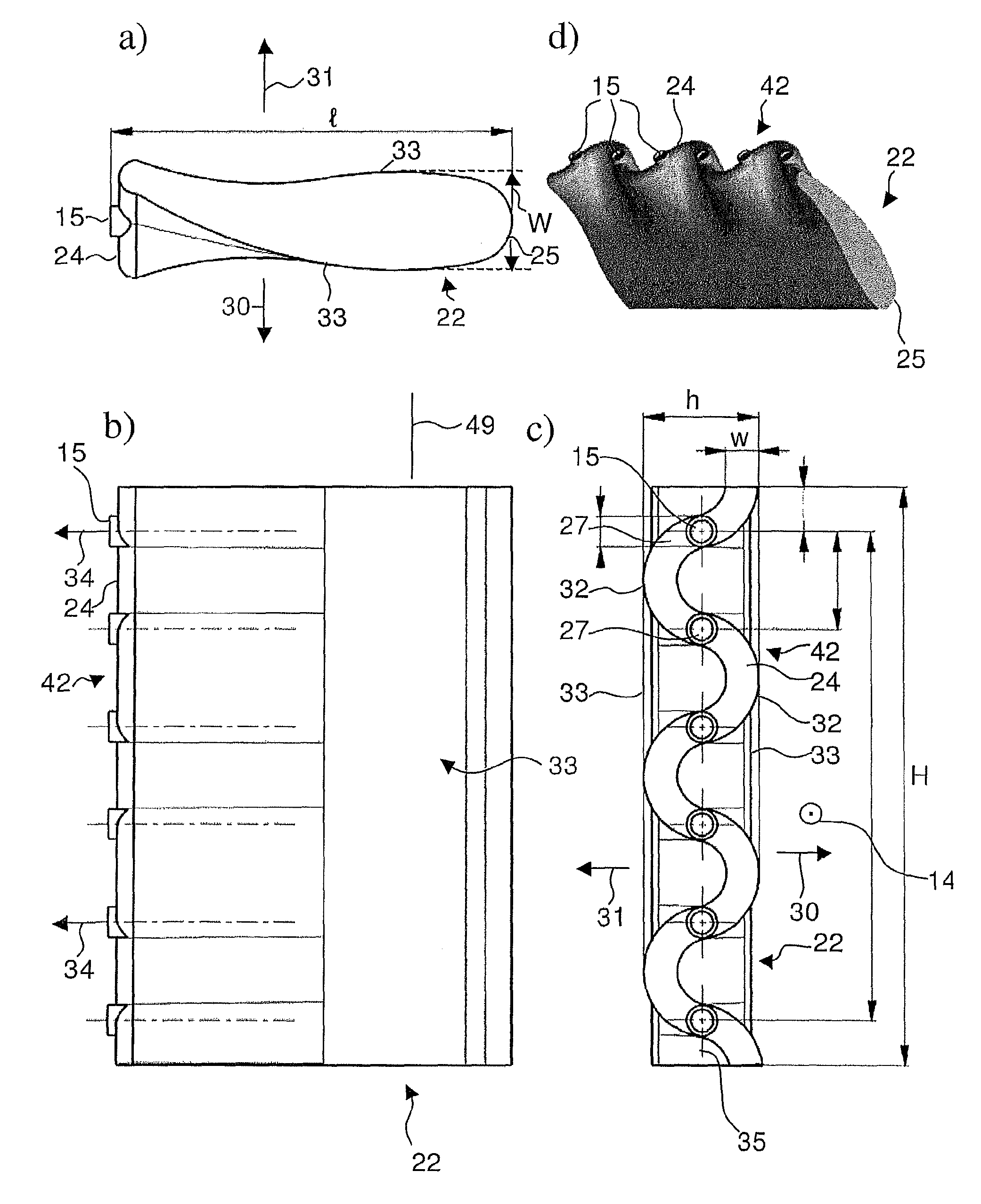
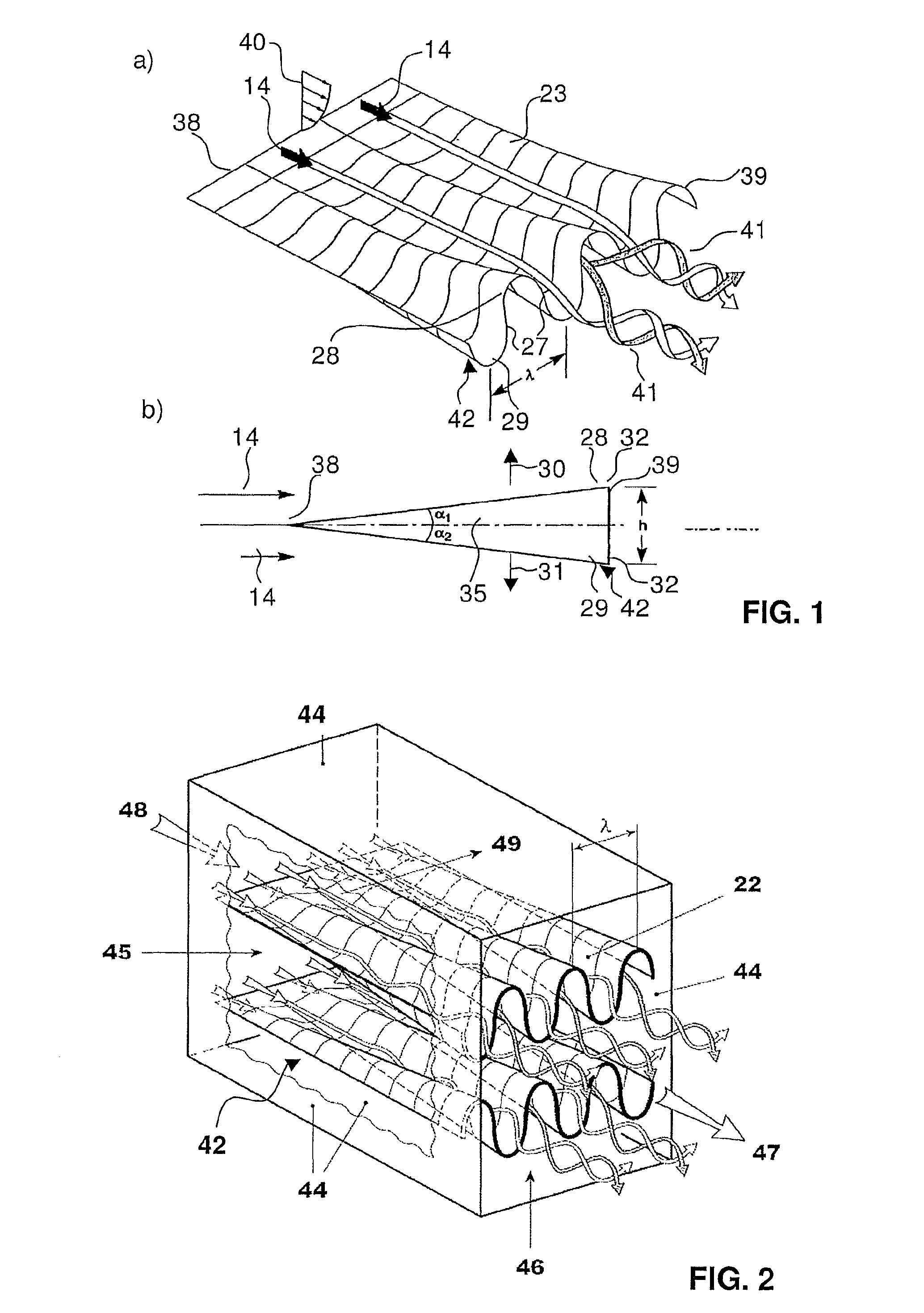
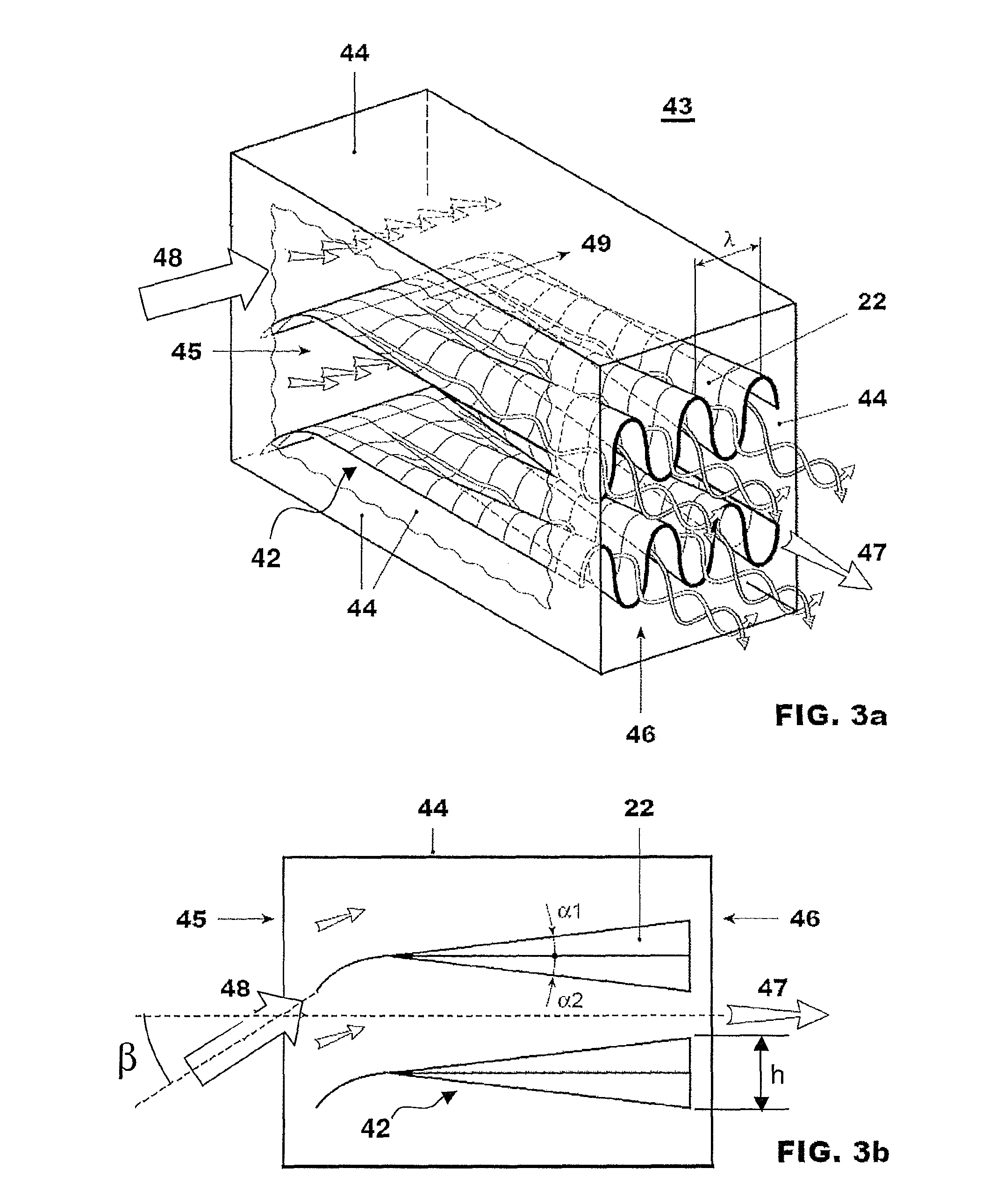
A combined flow straightener and mixer is disclosed as well as a burner for a combustion chamber of a gas turbine having such a mixing device. At least two streamlined bodies are arranged in a structure comprising the side walls of the mixer. The leading edge area of each streamlined body has a profile, which is oriented parallel to a main flow direction prevailing at the leading edge position, and with reference to a central plane of the streamlined bodies, the trailing edges are provided with at least two lobes in opposite transverse directions. The periodic deflections forming the lobes from two adjacent streamlined bodies are out of phase.
Description
RELATED APPLICATION[0001]This application claims priority under 35 U.S.C. §119 to Swiss Patent Application No. 00795 / 11 filed in Switzerland on May 11, 2011, the entire content of which is hereby incorporated by reference in its entirety.FIELD[0002]A combined flow straightener and mixer is disclosed, as well as a burner for a combustion chamber of a gas turbine having such a device. For example, a flow straightener and mixer can include with an injection device for the introduction of at least one gaseous and / or liquid.BACKGROUND INFORMATION[0003]Mixing devices are used for various technical applications. Optimization of mixing devices aims at reducing the energy used to obtain a specified degree of homogeneity. In continuous flow mixing the pressure drop over a mixing device is a measure for the energy involved. Further, the time and space used to obtain the specified degree of homogeneity can be important parameters when evaluating mixing devices or mixing elements. Static mixers ...
Claims
Login to View More Application Information
Patent Timeline
 Patent Type & AuthorityPatents(United States)
IPC IPC(8): F02K1/00B64D33/04B01F5/04B01F5/06F23D14/62F23R3/18F23R3/20F23R3/28F23R3/34
CPCF23R3/34B01F5/0451B01F5/0456B01F5/0463B01F5/0616F23D14/62F23R3/18F23R3/20F23R3/286F23R2900/03341B01F25/31322B01F25/31331B01F25/3131B01F25/4315
InventorPOYYAPAKKAM, MADHAVAN NARASIMHANSYED, KHAWARGAJULA, SATISH KUMARWOOD, JOHN PHILIP
OwnerANSALDO ENERGIA SWITZERLAND AG