Retractable Barrier System

a barrier system and retractable technology, applied in the direction of door/window protection devices, safety guards, shutters/movable grilles, etc., can solve the problems of increasing the size, weight and complexity of the residential type of compression gates described above, increasing the associated cost of manufacture, shipping, maintenance and repair of the same, and achieving quick and easy installation and removal and engaging and disengaging

Active Publication Date: 2017-10-05
GLIDE RITE CORP
View PDF0 Cites 25 Cited by
  • Summary
  • Abstract
  • Description
  • Claims
  • Application Information

AI Technical Summary

Benefits of technology

[0014]It is a principle object of the present invention to provide a portable and removable barrier system for use in inhibiting access to designated areas including private and public retail and warehouse aisles and the like, both indoor and outdoor, which system may be quickly and easily installed and removed and engaged and disengaged.
[0015]It is a further object of the present invention to provide a portable and removable barrier system for use in inhibiting access to such designated areas, which system is aesthetically pleasing and capable of implementation with conventional storage systems such as pallet racking systems or assemblies or other suitable receiving posts or brackets.
[0022]In a further preferred embodiment, a standoff portion may be coupled to the rotatable rod to provide bridged attachment over intervening objects at or near the rotatable rod and standoff portion, and / or permit the barrier system to be installed with proper alignment when one aperture of a corresponding receiving aperture pair is occupied or otherwise unavailable. In yet a further preferred embodiment, the standoff portion is provided with an adjustment mechanism such as a laterally or horizontally extendible and retractable hook to provide more secure coupling to the referenced receiving bracket or post aperture at or near the rotatable rod.

Problems solved by technology

In these retail and warehouse applications, the entryways and “aisles” defined by opposing post end sections of corresponding storage racks are typically substantially wider than residential entryways, and thus generally unsuitable for residential type compression gates of the type described above.
The aforementioned accordion gates, while effective and commonly used, by design comprise multiple movable accordion elements that increase the size, weight, and complexity of the corresponding gates, which in turn, correspondingly increases the associated costs of manufacture, shipping, maintenance and repair of the same.
Those skilled in the art will further recognize that the above referenced installation common to such accordion gates, namely securing the same at trailing edges in retracted storage positions with chains and flexible cord, may result in decreased visibility of products or signage stored or displayed in proximity to the gate, particularly at or near end caps or shelving units.
Still further, such accordion gates may extend or otherwise protrude, even in retracted, stored and secured positions, undesirable distances into corresponding entryways or aisles creating potential obstructions for shopping carts and machinery that may result in damage to the respective gates.
Lastly, such gates, by design, are generally unsuitable for pre-printed signage, such as may be useful for example, to notify persons of the presence of the gate (whether in the extended or storage position) or advise that the corresponding aisle or area has been temporarily closed.
Accordingly, retail and warehouse managers may be required to incur additional time and expense to obtain, post, and change such signage on or in proximity to such gates.
However, they still generally require fixed storage positions and may therefore extend or protrude into corresponding entryways and aisles during such storage thus creating potential obstructions to shopping carts and machinery and reducing customer or employee visibility of displayed product and signage.
Many such gate systems also require self-standing implementations wherein internal support posts are provided as part of the gate system thus raising concerns that the system may be removed or otherwise become inadvertently uninstalled.
In such case, the gate ends will be required to be affixed to different aperture rows (above or below the occupied rows) possibly requiring gate placement at different heights at the respective leading and trailing gate ends and resulting in misalignment of the gate once extended.

Method used


Image

  • Retractable Barrier System
  • Retractable Barrier System
  • Retractable Barrier System

Examples


Embodiment Construction

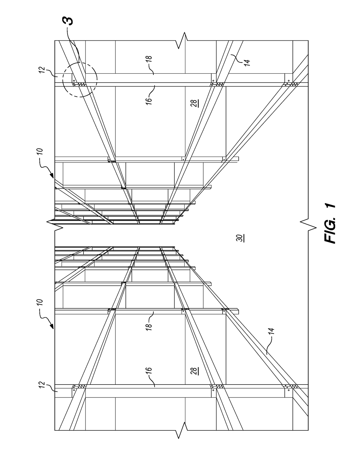
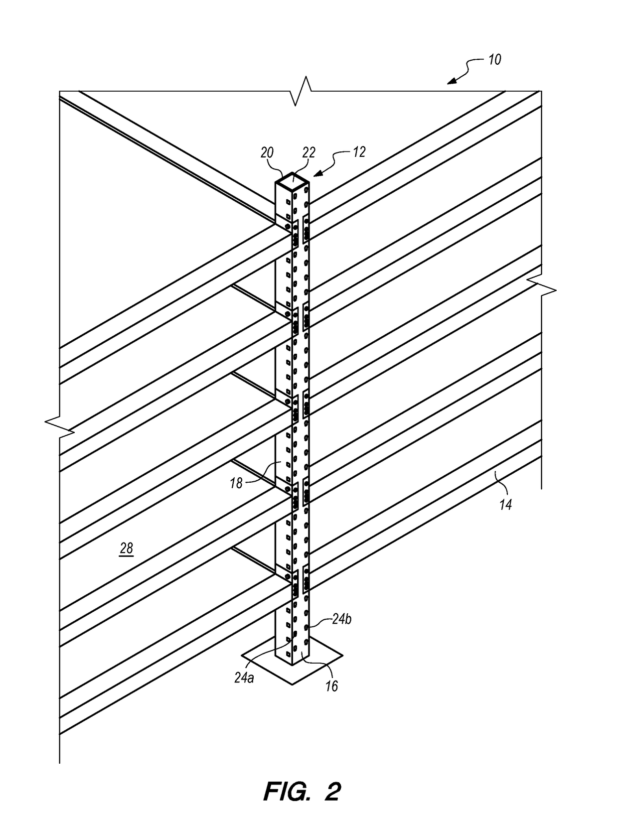
[0041]With reference to FIGS. 1-2 of the drawings, there is provided perspective diagrams of a conventional pallet rack shelving system or assembly 10 suitable for use with the present invention to block and inhibit access to private and public designated areas both indoors and outdoors including retail and warehouse aisles and the like. As those skilled in the art will recognize, assembly 10 includes a plurality of support posts 12 for receiving corresponding horizontal connecting lengths (not shown) and vertically spaced horizontal rack beams 14. Each support post 12 generally comprises a single piece of metal having an outwardly faced post section or margin 16, parallel side post sections or margins 18, and an opposed terminal end section or margin 20 defining a substantially square or rectangular post cross section 22.

[0042]As shown more fully in the exploded perspective view of FIG. 2, the outwardly facing post sections 16 and parallel post sections 18 are each typically provid...


PUM


Abstract

A retractable barrier system and method for inhibiting access to designated private and public areas both indoors and outdoor, including retail and warehouse aisles and the like, includes a flexible screen retractable and extensible from a rotatable rod coupled to a mounting member, the mounting member having an attachment mechanism for coupling with a receiving member such as storage rack assembly support post or bracket or the like.

Description

CROSS-REFERENCE TO RELATED APPLICATIONS[0001]None.TECHNICAL FIELD[0002]This invention relates generally to removable gates for temporarily inhibiting access to designated areas, and more particularly to a portable and retractable barrier system that may be quickly and easily installed and removed, and engaged and disengaged, as necessary to temporarily prevent access to such designated areas, including, retail and warehouse aisles, checkout aisles, and other private and public spaces both indoors and outdoors.BACKGROUND ART[0003]Removable gates, particularly child and pet safety gates, are well known in the art for use in preventing access to residential areas considered unsafe or undesirable for children or pets. Conventional gates characteristically comprise a plurality of cooperating gate sections that are generally horizontally extensible and retractable within narrow entryways such as between doorjambs, opposed walls, and balustrade uprights, and the like. These safety gates ar...

Claims


Application Information

Patent Timeline
Patent Type & Authority Applications(United States)
IPC IPC(8): E06B9/17E06B9/78E06B9/60A47H1/13
CPCE06B9/17A47H1/13E06B2009/002E06B9/78E06B9/60E06B9/17007A47F5/101A47F11/02E06B9/40
Inventor REINER, ANDREW ERICROSE, THOMAS JAMES
Owner GLIDE RITE CORP
Why Eureka
Try Eureka