Common mode filter
a filter and modem technology, applied in the direction of transformer/inductance magnetic cores, inductances, impedence networks, etc., can solve the problems of inability to meet the needs of increasing the length low utilization efficiency of the winding core part, etc., to achieve higher signal balance, improve signal balance, and improve the effect of signal balan
- Summary
- Abstract
- Description
- Claims
- Application Information
AI Technical Summary
Benefits of technology
Problems solved by technology
Method used
Image
Examples
first embodiment
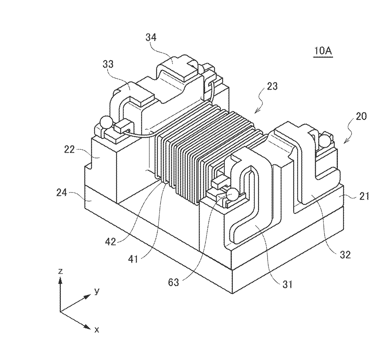
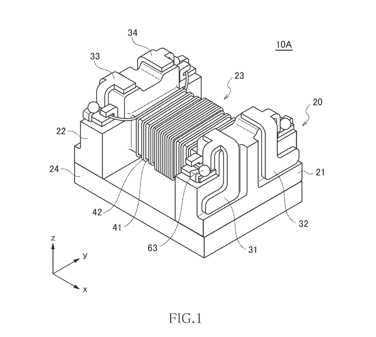
[0031]FIG. 1 is a schematic perspective view illustrating the outer appearance of a common mode filter 10A according to the first embodiment of the present invention.
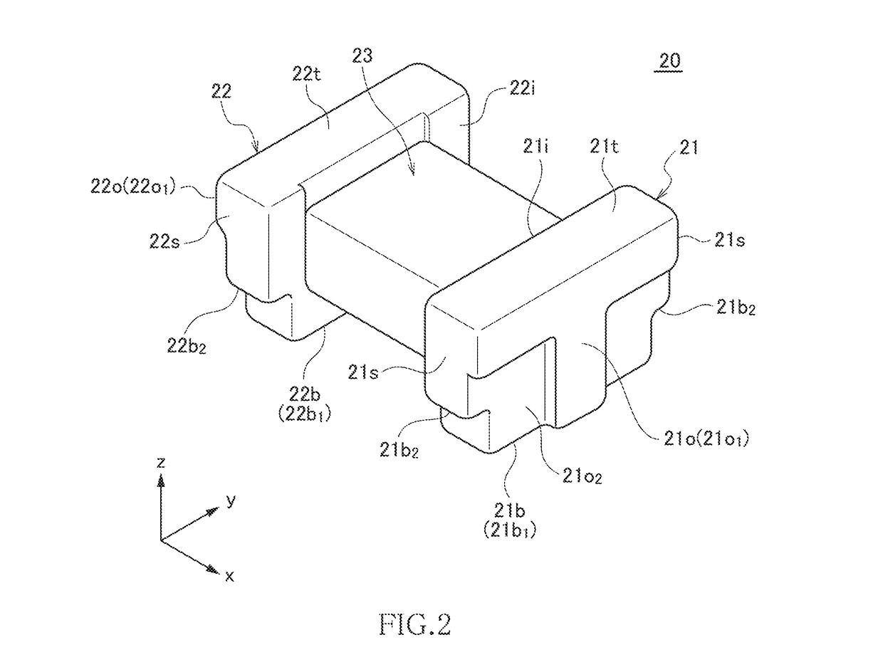
[0032]As illustrated in FIG. 1, the common mode filter 10A according to the present embodiment includes a drum core 20, a plate core 24, first to fourth terminal electrodes 31 to 34, and first and second wires 41 and 42. The structure of the core 20 is illustrated in FIG. 2, and the structure of the first terminal electrode 31 is illustrated in FIG. 3. The cores 20 and 24 are each formed of a magnetic material having a comparatively high permeability, such as an Ni—Zn based ferrite. The first to fourth terminal electrodes 31 to 34 are each a metal fitting formed of a good conductor material such as copper.
[0033]The core 20 has a first flange part 21, a second flange part 22, and a winding core part 23 disposed between the first and second flange parts 21 and 22. The winding core part 23 has its axis direction in the x-d...
second embodiment
[0049]FIG. 5 is a schematic view for explaining the winding layout in a common mode filter 10B according to the second embodiment of the present invention.
[0050]As illustrated in FIG. 5, the common mode filter 10B according to the present embodiment differs from the common mode filter 10A according to the first embodiment in the winding layout in the third winding region 73. Other basic configurations are the same as those of the common mode filter 10A according to the first embodiment, so the same reference numerals are given to the same elements, and overlapping description will be omitted.
[0051]In the present embodiment, the third winding region 73 includes first and second layer regions 81 and 82, and the first and second wires 41 and 42 cross each other at a cross point 83 positioned between the first and second layer regions 81 and 82. The first layer region 81 is positioned on the first winding region 71 side, where the first and second wires 41 and 42 are each wound in five ...
third embodiment
[0059]FIG. 11 is a schematic view for explaining the winding layout in a common mode filter 10C according to a third embodiment of the present invention.
[0060]As illustrated in FIG. 11, the common mode filter 10C according to the present embodiment differs from the common mode filter 10B according to the second embodiment in the winding layout in the third winding region 73. Other configurations are the same as those of the common mode filter 10B according to the second embodiment, so the same reference numerals are given to the same elements, and overlapping description will be omitted.
[0061]In the present embodiment, in both the first and second layer regions 81 and 82, the first wire 41 is wound in the lower layer, and the second wire 42 is wound on the first wire 41. However, as described above, in the layer winding, one turn of the wire to be wound in the upper layer is dropped to the lower layer. Thus, in the present embodiment, one turn of the second wire 42 is dropped to the...
PUM
| Property | Measurement | Unit |
|---|---|---|
| distance | aaaaa | aaaaa |
| parasitic capacitance | aaaaa | aaaaa |
| high-frequency characteristics | aaaaa | aaaaa |
Abstract
Description
Claims
Application Information
 - R&D
- Intellectual Property
- Life Sciences
- Materials
- Tech Scout
- Unparalleled Data Quality
- Higher Quality Content
- 60% Fewer Hallucinations
Browse by: Latest US Patents, China's latest patents, Technical Efficacy Thesaurus, Application Domain, Technology Topic, Popular Technical Reports.
© 2025 PatSnap. All rights reserved.Legal|Privacy policy|Modern Slavery Act Transparency Statement|Sitemap|About US| Contact US: help@patsnap.com


