Tin silicon anode active material

a silicon anode and active material technology, applied in the direction of cell electrodes, electrochemical generators, electric devices, etc., can solve the problems of cell breakdown and possible fire or explosion, fire and safety risks, and thermal runaway

Active Publication Date: 2017-10-12
STOREDOT
View PDF1 Cites 60 Cited by
  • Summary
  • Abstract
  • Description
  • Claims
  • Application Information

AI Technical Summary

Benefits of technology

The invention is a simplified summary of a patent text that introduces the reader to the text without identifying key elements or limiting the scope of the invention. The technical effect of the invention is to provide a more accessible and understandable summary of the patent text for the reader.

Problems solved by technology

The technical problem addressed in this patent text is the safety concerns associated with batteries, particularly lithium ion batteries, which can overheat, overcharge, or short-circuit, leading to thermal runaway and potential fire or explosion. These risks are particularly significant when batteries are used in electronic devices that may come into contact with humidity.

Method used


Image

  • Tin silicon anode active material
  • Tin silicon anode active material
  • Tin silicon anode active material

Examples


Embodiment Construction

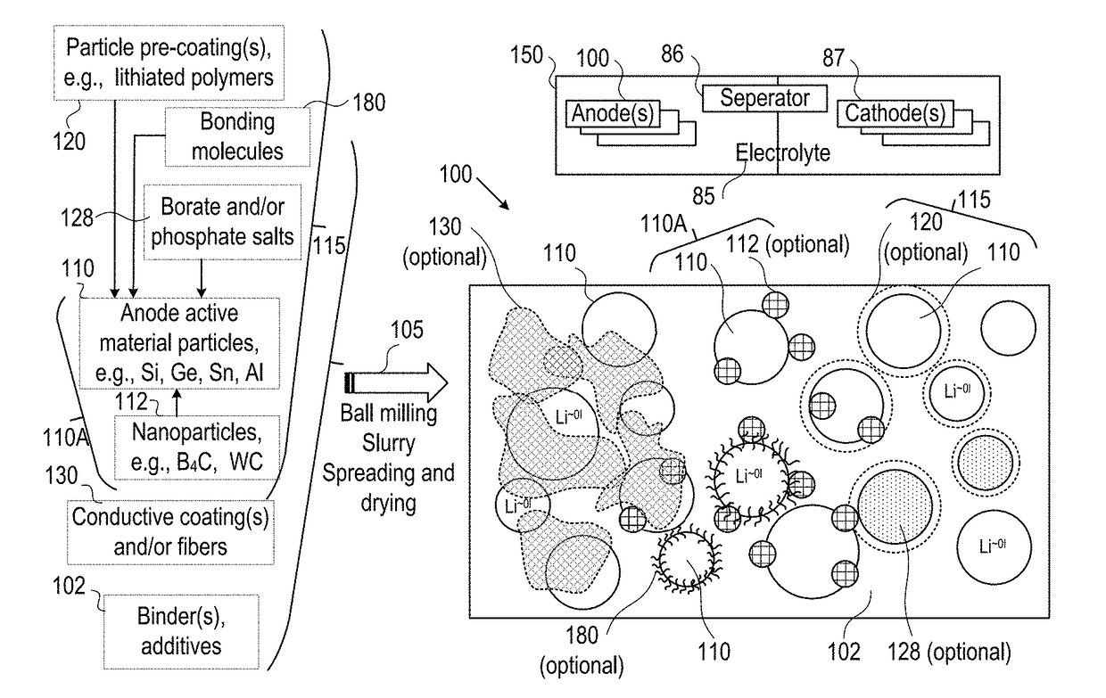
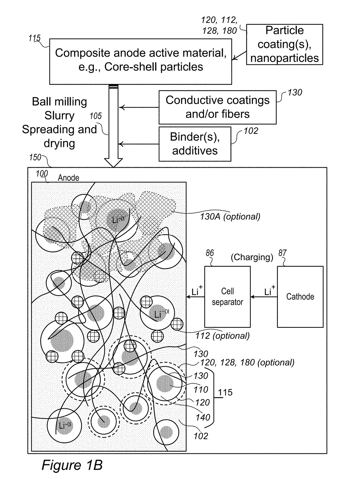
[0039]In the following description, various aspects of the present invention are described. For purposes of explanation, specific configurations and details are set forth in order to provide a thorough understanding of the present invention. However, it will also be apparent to one skilled in the art that the present invention may be practiced without the specific details presented herein. Furthermore, well known features may have been omitted or simplified in order not to obscure the present invention. With specific reference to the drawings, it is stressed that the particulars shown are by way of example and for purposes of illustrative discussion of the present invention only, and are presented in the cause of providing what is believed to be the most useful and readily understood description of the principles and conceptual aspects of the invention. In this regard, no attempt is made to show structural details of the invention in more detail than is necessary for a fundamental u...


PUM


Abstract

Improved anodes and cells are provided, which enable fast charging rates with enhanced safety due to much reduced probability of metallization of lithium on the anode, preventing dendrite growth and related risks of fire or explosion. Anodes and/or electrolytes have buffering zones for partly reducing and gradually introducing lithium ions into the anode for lithiation, to prevent lithium ion accumulation at the anode electrolyte interface and consequent metallization and dendrite growth. Various anode active materials and combinations, modifications through nanoparticles and a range of coatings which implement the improved anodes are provided.

Description


Claims


Application Information

Patent Timeline
Owner STOREDOT
Why Eureka
Try Eureka