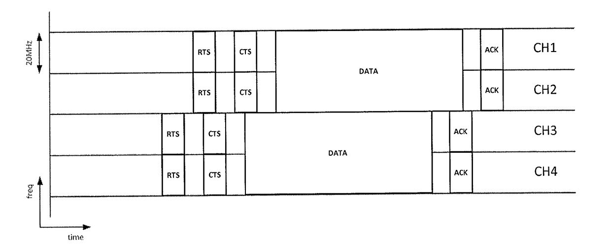
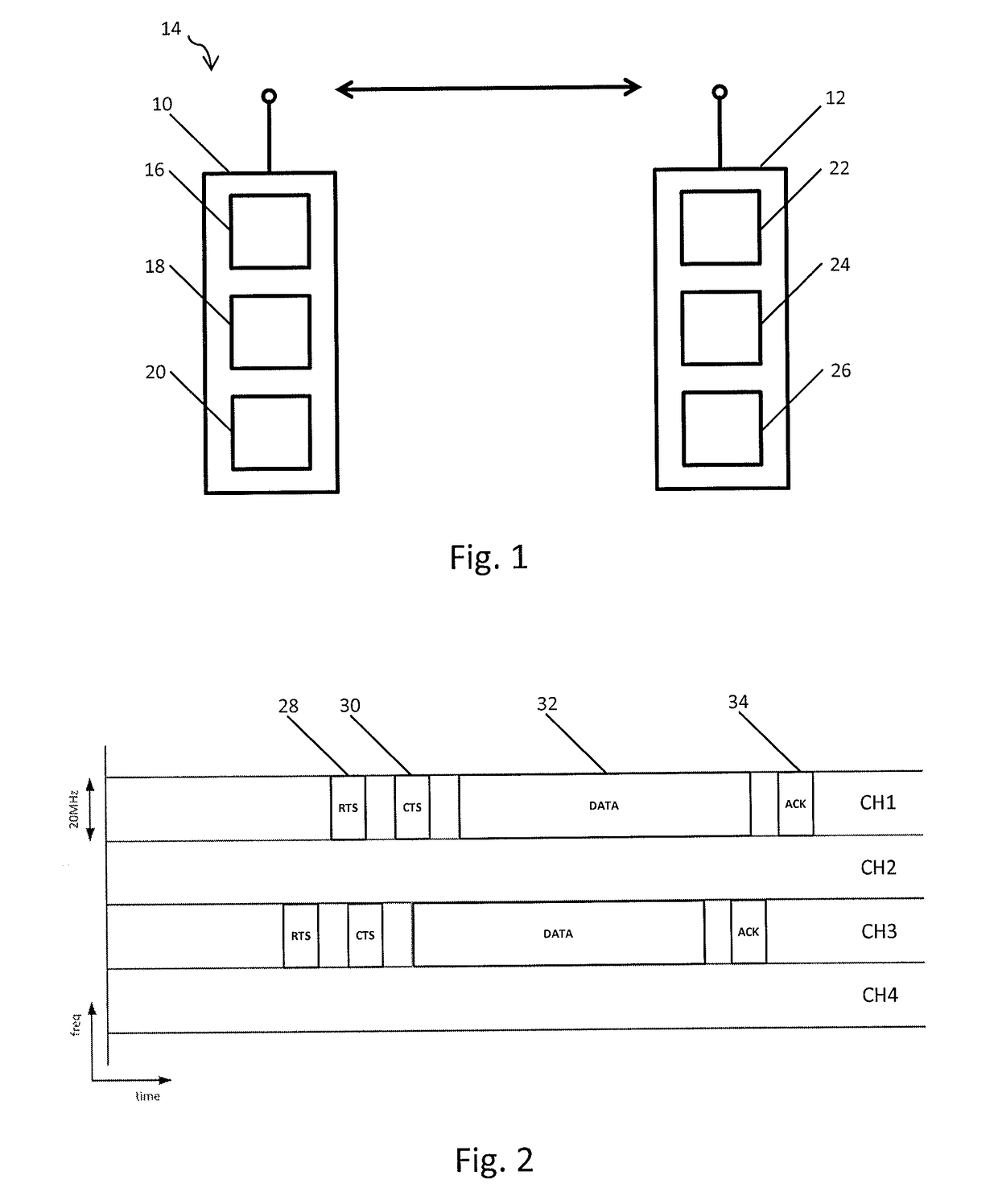
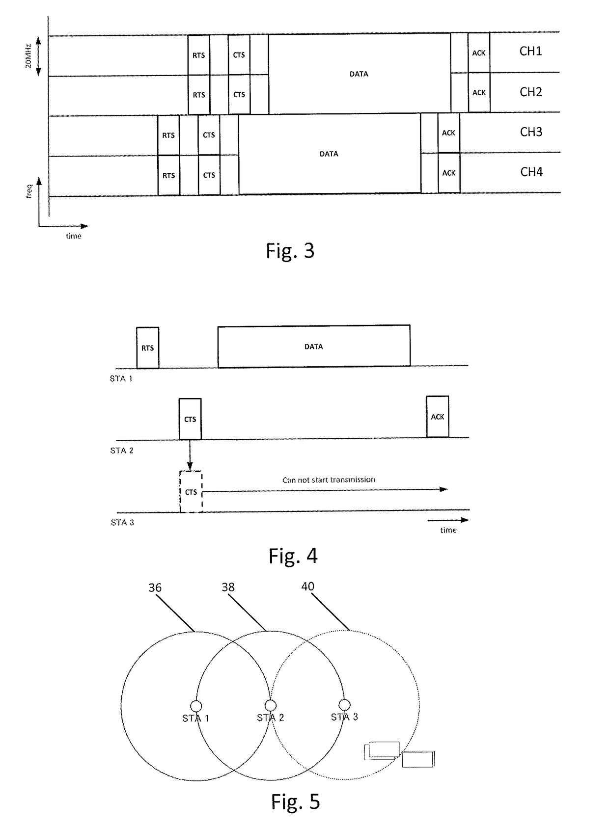
Transmitter and receiver for multiple channel operation
a receiver and transmitter technology, applied in the field of transmitters and receivers for multiple channel operation, can solve the problems of difficult to find wide contiguous frequency resources for transmitting multichannel packets, crowded operation channels (wireless frequencies), etc., and achieves the effect of improving coexistence of different wifi systems, high data rate, and high flexibility
- Summary
- Abstract
- Description
- Claims
- Application Information
AI Technical Summary
Benefits of technology
Problems solved by technology
Method used
Image
Examples
embodiment 1
2. The transmitter as defined in embodiment 1, wherein
[0066]the transmitting unit is configured to transmit the request packet via a channel in the candidate channel list.
3. The transmitter as defined in any preceding embodiment, wherein
[0067]the transmitting unit is configured to transmit the request packet via all channels in the candidate channel list.
4. The transmitter as defined in any preceding embodiment, wherein
[0068]the transmitting unit is configured to transmit the data packet via a combined channel corresponding to a combination of at least two contiguous or non-contiguous channels of the selected channels when the response packet is received via at least two selected channels.
5. The transmitter as defined in any preceding embodiment, wherein
[0069]the request packet further includes a unique code and / or a unique timing corresponding to the receiver; and
[0070]the transmitting unit is configured to identify the receiver from which a response packet is received via at least...
embodiment 5
6. The transmitter as defined in embodiment 5, wherein
[0071]the transmitting unit is configured to transmit to said identified receiver a data packet intended for said identified receiver via the at least one selected channel included in the candidate channel list.
7. The transmitter as defined in any preceding embodiment, wherein
[0072]the transmitting unit and the receiving unit are configured to transmit and receive packets in compliance with the IEEE 802.11 standard; and / or
[0073]the at least one channel in the candidate channel list is determined based on the channels as specified by the IEEE 802.11 standard.
8. The transmitter as defined in any preceding embodiment, wherein
[0074]the transmitting unit is configured to transmit a data packet to a plurality of receivers via a channel being available for reception at each receiver of the plurality of receivers.
9. The transmitter as defined in any preceding embodiment, wherein
[0075]the transmitting unit is configured to transmit the da...
embodiment 10
11. The receiver as defined in embodiment 10 wherein
[0080]the receiving unit is configured to receive the request packet via a channel in the candidate channel list.
12. The receiver as defined in any of the embodiments 9-11, wherein
[0081]the receiving unit is configured to receive the request packet via all channels in the candidate channel list.
13. The receiver as defined in any of the embodiments 9-12, wherein
[0082]the receiving unit is configured to receive the data packet via a combined channel corresponding to a combination of at least two contiguous or non-contiguous channels of the selected channels when the response packet is transmitted via at least two selected channels.
14. The receiver as defined in any of the embodiments embodiment 9-13, wherein
[0083]the request packet further includes a unique code and / or a unique timing corresponding to the receiver; and
[0084]the transmitting unit is configured to apply the unique code to the response packet prior to transmitting the r...
PUM
 Abstract
Description
Claims
Application Information
 - R&D
- Intellectual Property
- Life Sciences
- Materials
- Tech Scout
- Unparalleled Data Quality
- Higher Quality Content
- 60% Fewer Hallucinations
Browse by: Latest US Patents, China's latest patents, Technical Efficacy Thesaurus, Application Domain, Technology Topic, Popular Technical Reports.
© 2025 PatSnap. All rights reserved.Legal|Privacy policy|Modern Slavery Act Transparency Statement|Sitemap|About US| Contact US: help@patsnap.com


