[0015] In view of the foregoing, embodiments of the present invention provide a system,
assembly,
software, and related methods provide real-time, full-
time data obtained through an online sensor
package including a measurement instrument module having gyroscopes and accelerometers, deployable at a discrete location adjacent top and / or bottom locations of the riser, and that provide data which is dynamically accurate and which can be used in all riser
modes of operation including installation, drilling, non-drilling, production, disconnect, and retrieval, to allow real-
time management of the riser system. Embodiments of the present invention can include a high-speed subsea network backbone and that can utilize both a riser lower portion angle (RLPA) and a riser upper portion angle (RUPA) differential for modeling the dynamic shape of the riser, providing dynamic three-dimensional angular position and orientation of the riser, which can be referenced to a globally assigned coordinate system. Advantageously, the directional information can be provided in terms of
True North, rather than merely being referenced to a local coordinate system assigned to the measurement instrument module unit itself. Advantageously, this configuration enhances seamless integration with other globally based systems.
[0016] Riser measurement instrument modules can communicate data to the surface via a high data-rate media such as
fiber optics, electric cabling, or high data E / H or
acoustics. Data transmitted includes
angular acceleration,
angular velocity,
angular displacement, liner acceleration, linear velocity,
linear displacement and heading. Heading can be computed by the
digital signal processor based on acceleration measurements. The data can be received in real-time and can be displayed and stored cyclically for retrieval. This data can provide highly accurate riser joint angles and riser dynamic information at high data rates.
[0017] Embodiments of the present invention also can utilize the
umbilical cord for a
blowout preventer (“BOP”), a lower marine riser
package (“LMRP”), or other subsea equipment to provide power and
data transmission capability for the measurement instrument module or modules located adjacent the
wellhead system. Further, vessel power and data transmission capability can be utilized for a measurement instrument module located adjacent to the vessel. This negates a need for providing a separate data or
power transmission line or providing taps into the
umbilical cord. Embodiments of the present invention include
software that can determine an angular differential between a bottom location of the riser and the wellhead / wellhead conductor, and angular differential between a top location of the riser and a surface vessel carrying the riser, and an angular differential between the top and bottom locations of the riser. The software can also model the riser structure between the top and bottom locations of the riser.
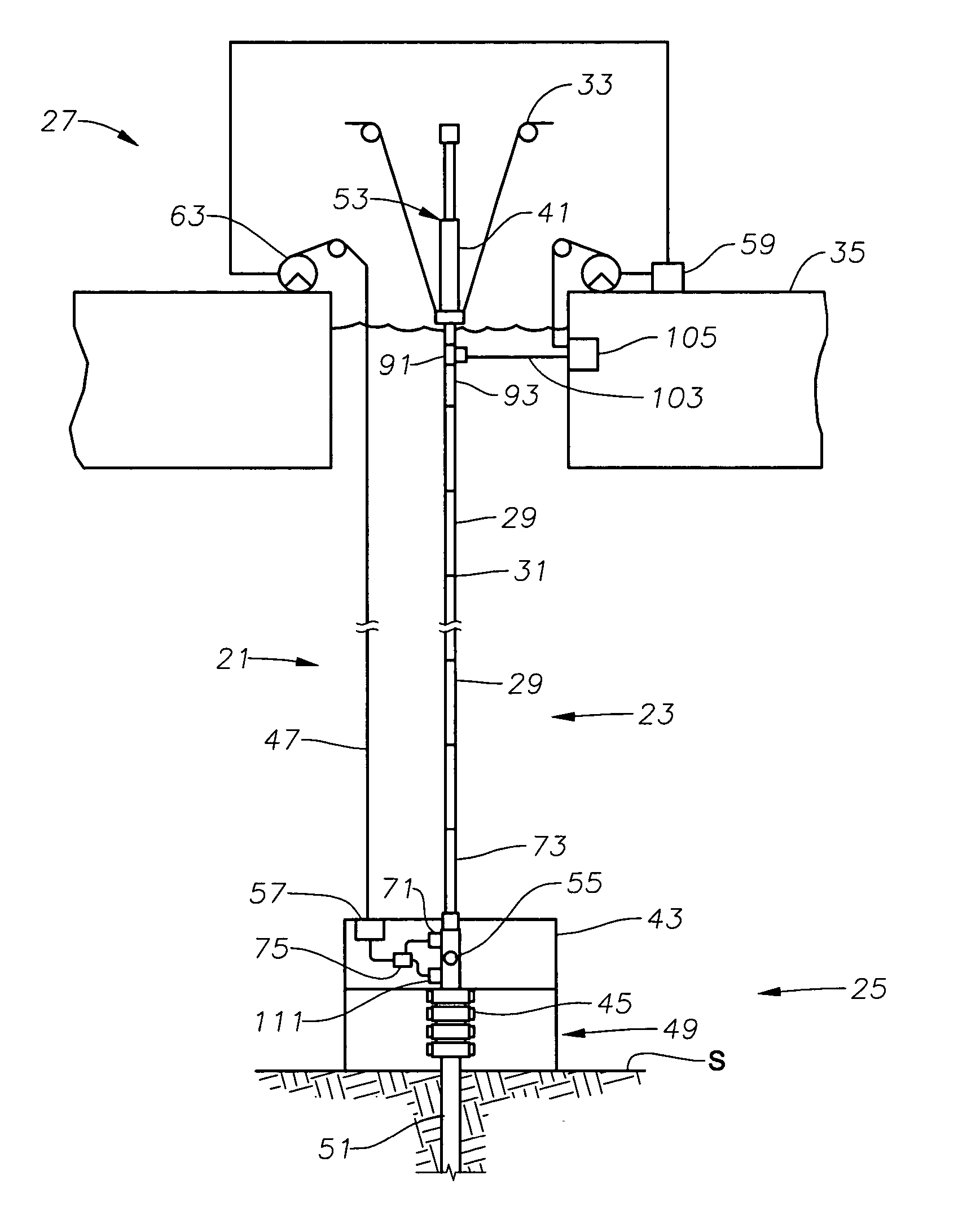
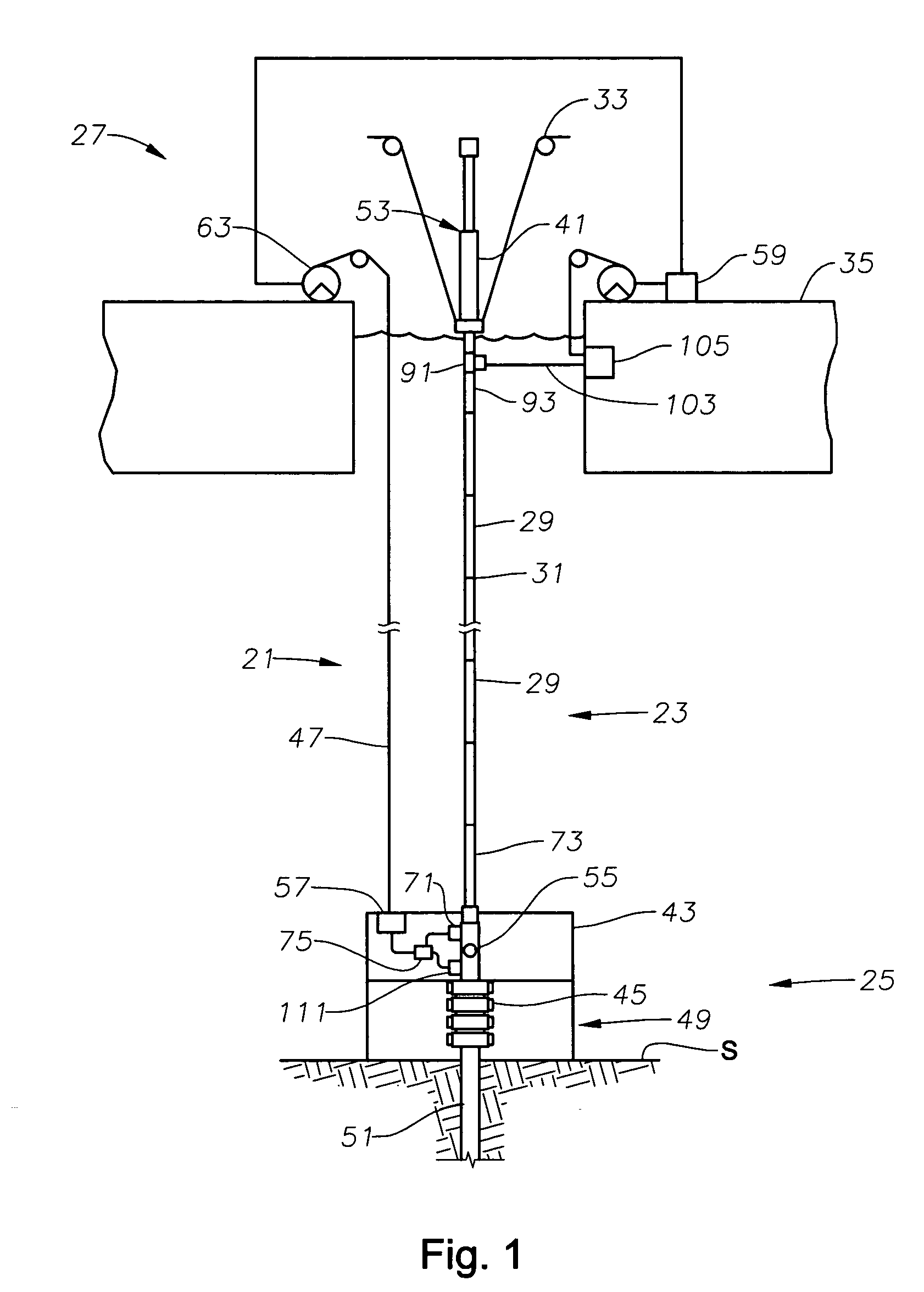
[0019] Riser dynamics can be determined from a measurement instrument module located near the surface, preferably adjacent the upper or proximal portion of the riser, and / or a measurement instrument module located subsea preferably adjacent the lower or
distal portion of the riser. The measurement instrument modules are of such a configuration, generally in the form of a self-contained
inertial navigation system, that additional intermediate measurement instrument modules are generally not required. Advantageously, the physical positioning of the subsea measurement instrument module, preferably connected adjacent an upper section of a lower flex joint (if the riser is so configured), allows such module to connect with the
umbilical cord termination
bottle (
junction box) associated with the LMRP or other nearby subsea equipment to thereby communicate with the surface through the umbilical cord. Correspondingly, advantageously this riser measurement instrument module configuration allows the
surface measurement instrument module, preferably connected adjacent a lower section of an upper flex joint (if the riser is so configured), to connect with the vessel network, directly, rather than through the umbilical cord. Thus, this riser measurement instrument module configuration advantageously negates the need for a separate data line or for taps along the length of the data line, which would need to be fitted with terminators if a section of riser having such an intermediate measurement instrument, were removed, replaced, or rotated.
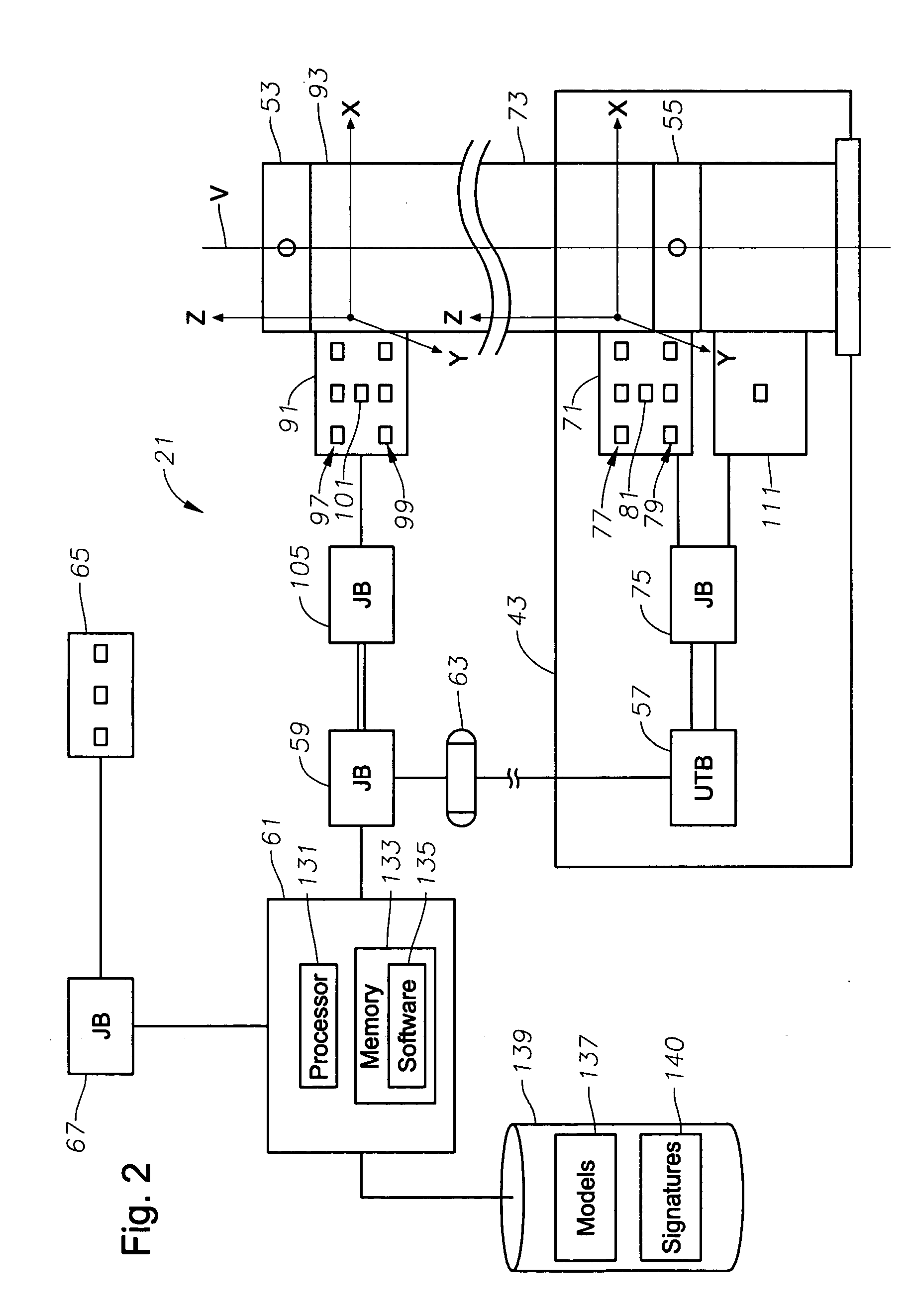
[0020] The measurement instrument modules can provide real-time dynamic three-dimensional position and orientation data which can be used to determine a tilt and heading for a respective riser lower portion and riser upper portion. To prevent the necessity for a separate umbilical cord to house a high-speed communication line for the subsea riser management instrument module in a riser having a LMRP, the module can be electrically connected to a LMRP riser
management system interface or
junction box which can be both electrically and / or optically connected to the umbilical cord termination
bottle. Note, in an alternate configuration, the module can be connected directly to the umbilical cord termination
bottle.
[0024] The riser
management system analyzing software can utilize real-time measured environmental states and the real-time measured relative position and orientation of the lower, upper, or medial portions or sections of the riser. Riser position and orientation can be determined from the data provided by the measurement instrument modules and riser model structures organized in the table of models to allow a manager to analyze the riser dynamic behavior, and thus, determine a model of the real-
time structure of the riser. Riser position and orientation can also be used to supplement determination and management of the position of the vessel with respect to the wellhead. The riser position and orientation along with or in addition to riser vibration data further can allow the manager to determine and manage the existence of vortex induced vibration, and determine stress levels in individual riser sections.

