
Backlight module and display device

Active Publication Date: 2017-10-26
BOE TECH GRP CO LTD +1
View PDF8 Cites 7 Cited by
  • Summary
  • Abstract
  • Description
  • Claims
  • Application Information

AI Technical Summary

Benefits of technology

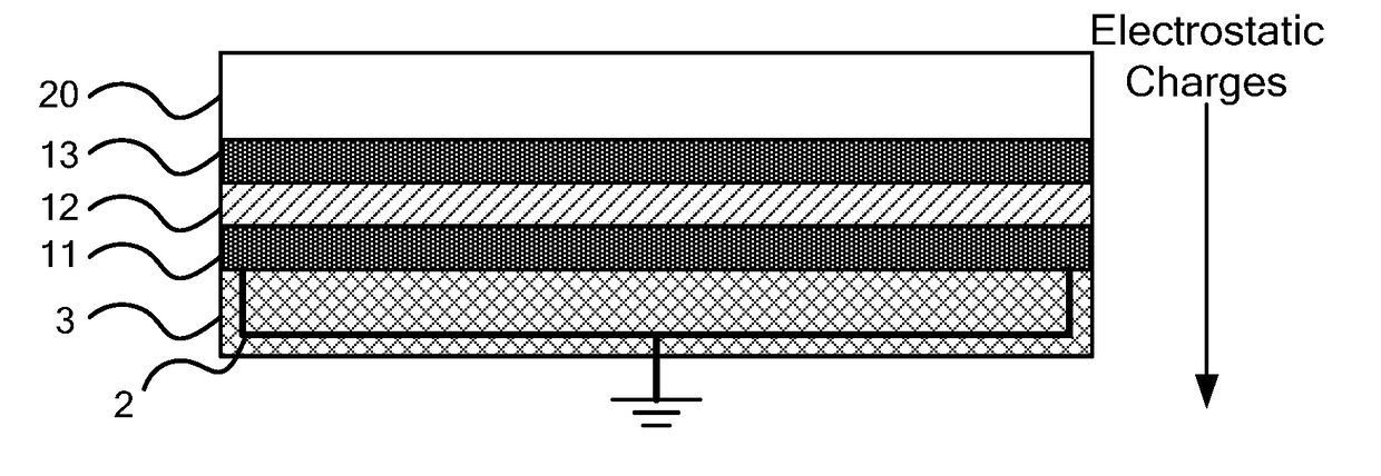
The present invention provides a solution for reducing electrostatic charges in display panels. The technique involves using a conductive adhesive tape to lead the electrostatic charges out of the display panel and into the backlight module, without the need for additional wires. This simplifies the arrangement of the electrostatic charge leading-out structure. Additionally, when performing an electrostatic charge discharge test on the display panel, the conductive adhesive tape contacting the light bar helps to quickly transfer the electrostatic charges to the light bar and out of the display panel, improving the throughput rate of the test.

Problems solved by technology

ESD (electrostatic discharge) will occur in interior of an existing display device including a display panel and a backlight module due to factors such as manufacturing processes or environment, and if electrostatic charges could not be quickly and efficiently led out, accumulation of more electrostatic charges may result in a higher electrostatic voltage in a local portion of the display device, for example in a local portion of the display panel or the backlight module and thus in a larger discharging current, which will cause damage to circuits or configurations of the display panel or backlight module.

Method used


Image

  • Backlight module and display device
  • Backlight module and display device
  • Backlight module and display device

Examples


Embodiment Construction

[0035]In order to provide a more clear understanding of above objects, features and advantages of the present disclosure, the present disclosure will be further described hereinafter in detail in conjunction with preferred embodiments and with reference to the attached drawings. It is noted that embodiments and features thereof of the present disclosure may be randomly combined without conflicting.

[0036]Further, in the following detailed description, for purposes of explanation, numerous specific details are set forth in order to provide a thorough understanding of the present disclosure. It will be apparent, however, that the present disclosure may also be implemented in other ways different from those described herein. Thus, scopes of the present invention will not be limited to the following disclosed exemplary embodiments.

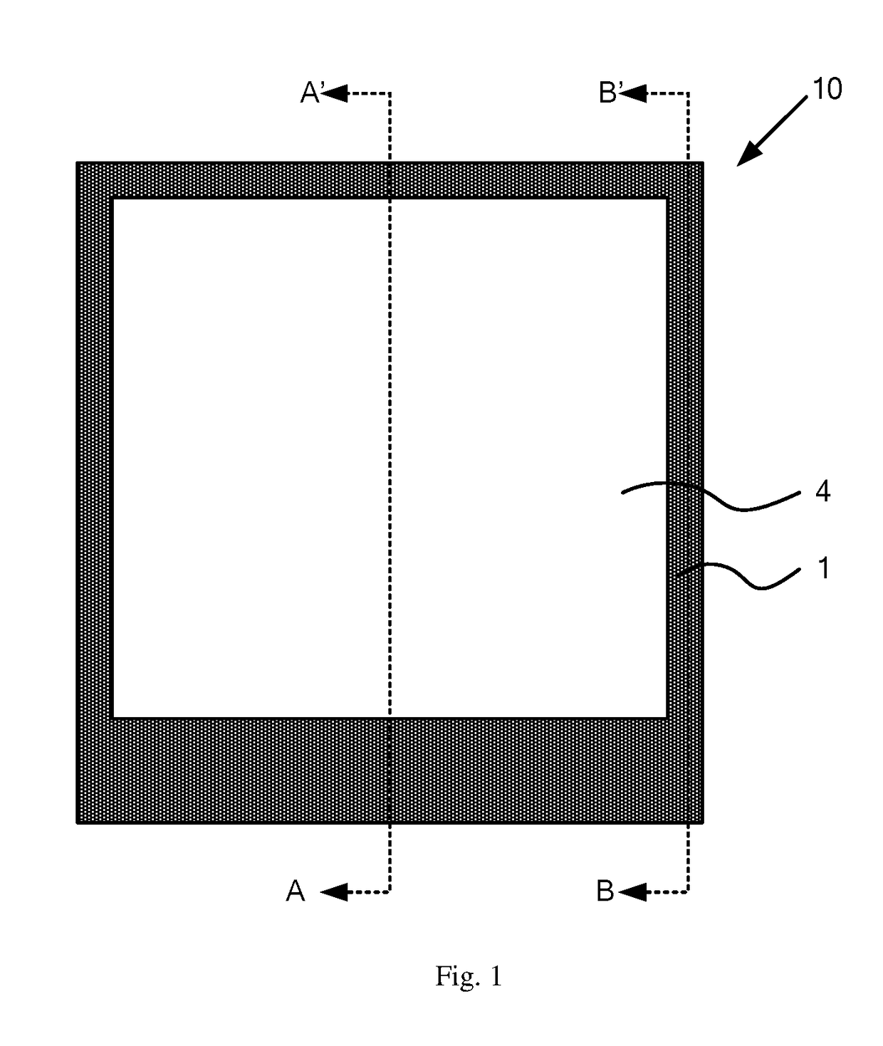
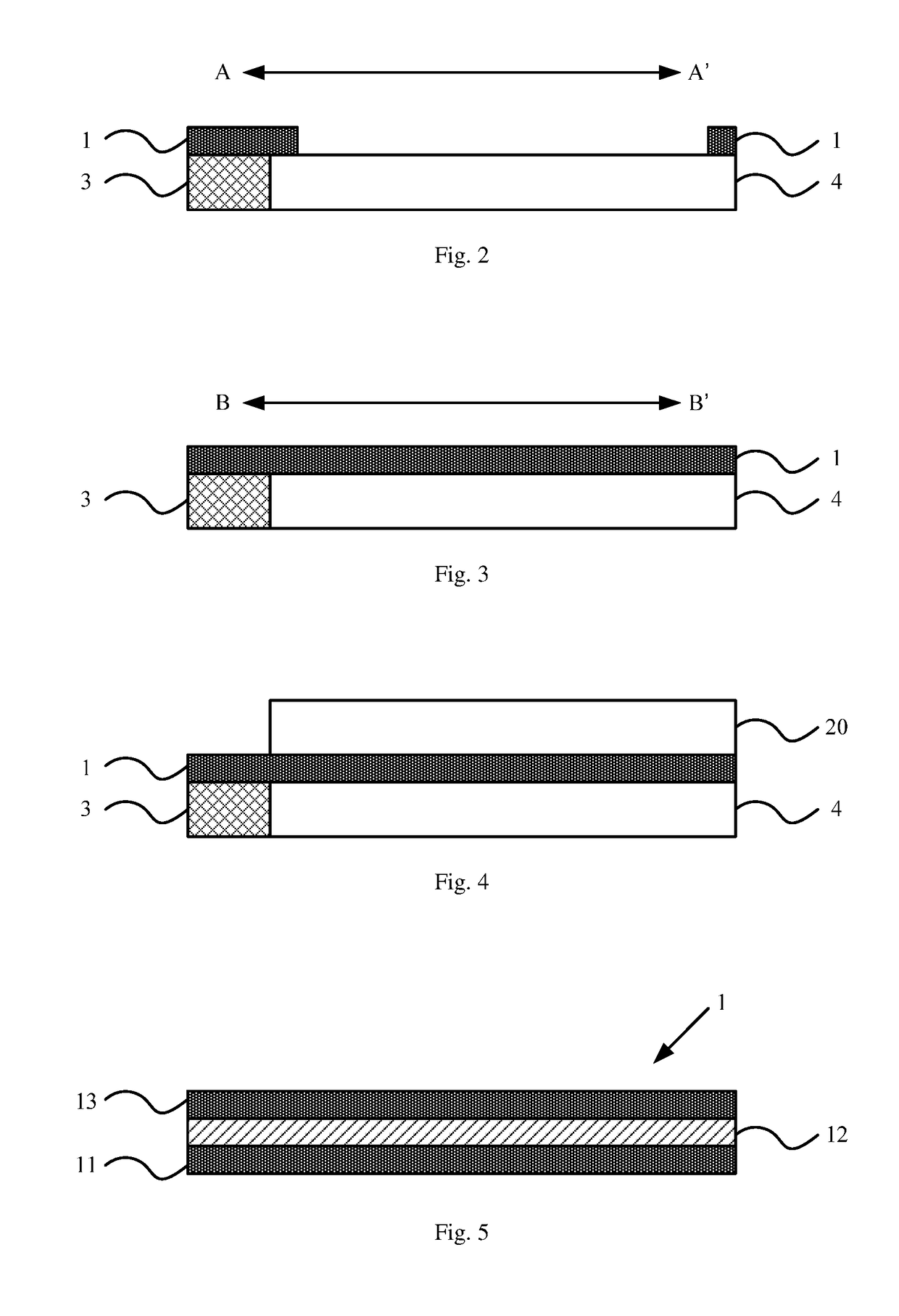
[0037]As shown in FIG. 1 to FIG. 7, a backlight module 10 according to an exemplary embodiment of the present disclosure comprises:

[0038]a conductive adhesive ...


PUM


Abstract

The disclosure relates to a backlight module and a display device. The backlight module includes: a conductive adhesive tape configured for adhering the backlight module to a display panel to transfer electrostatic charges in the display panel to the backlight module; and a first wire configured to lead the electrostatic charges out from the backlight module, the electrostatic charges led out from the backlight module at least including the electrostatic charges transferred from the display panel to the backlight module, electrostatic charges generated in the backlight module, or a combination thereof. Electrostatic charges in the display panel are led into the backlight module through the conductive adhesive tape, and are led out via the first wire of the backlight module, so that no wire needs to be provided in the display panel for leading out the electrostatic charges, that is, it is not necessary to adjust wirings in the display panel.

Description

CROSS-REFERENCE TO RELATED APPLICATION[0001]This application is a Section 371 National Stage Application of International Application No. PCT / CN2016 / 075829, filed on 8 Mar. 2016, entitled “BACKLIGHT MODULE AND DISPLAY DEVICE”, which has not yet published, and which claims priority to Chinese Application No. 201510605299.8, filed on 21 Sep. 2015, incorporated herein by reference in their entirety.BACKGROUNDTechnical Field[0002]Embodiments of the present disclosure generally relate to the field of display technologies, and particularly, to a backlight module and a display device.Description of the Related Art[0003]ESD (electrostatic discharge) will occur in interior of an existing display device including a display panel and a backlight module due to factors such as manufacturing processes or environment, and if electrostatic charges could not be quickly and efficiently led out, accumulation of more electrostatic charges may result in a higher electrostatic voltage in a local portion ...

Claims


Application Information

Patent Timeline
IPC IPC(8): F21V8/00H05F3/02
CPCG02B6/0093H05F3/02G02B6/0083F21S8/00F21V19/001F21V23/002G09F9/00
Inventor GAO, LIANGZHANG, GONGTAOSUN, HAIWEISANG, JIANCAI, XIUJUNDI, SHUANHUMA, JUNJIE
Owner BOE TECH GRP CO LTD
Learn More