Wide-Angle Lens Assembly
a technology of wide-angle lens and assembly, which is applied in the direction of optics, instruments, optical elements, etc., can solve the problems that the known wide-angle lens cannot meet such requirements, and achieve the effects of reducing f-number, reducing total lens length, and widening field of view
- Summary
- Abstract
- Description
- Claims
- Application Information
AI Technical Summary
Benefits of technology
Problems solved by technology
Method used
Image

Examples
first embodiment
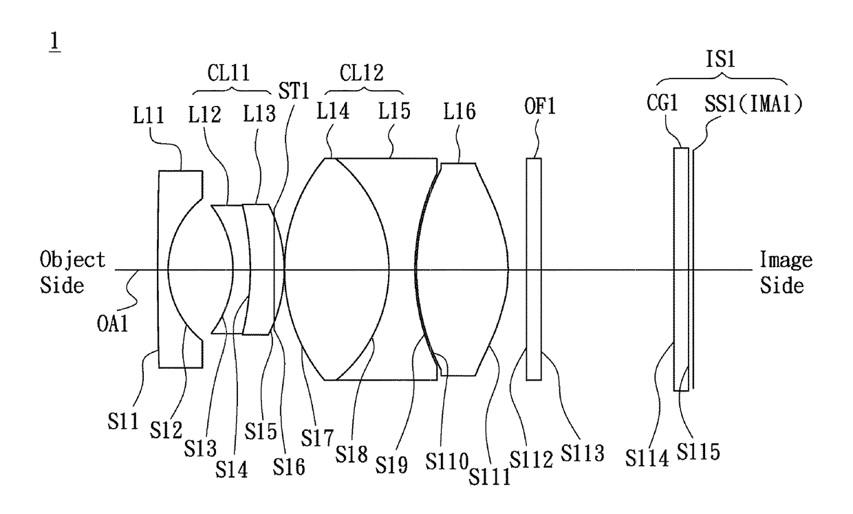
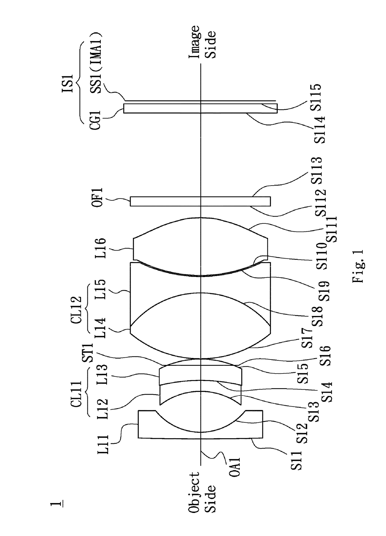
[0038]Referring to FIG. 1, FIG. 1 is a lens layout diagram of a wide-angle lens assembly in accordance with the invention. The wide-angle lens assembly 1 includes a first lens L11, a second lens L12, a third lens L13, a stop ST1, a fourth lens L14, a fifth lens L15, a sixth lens L16 and an optical filter OF1, all of which are arranged in order from an object side to an image side along an optical axis OA1. An image sensor IS1 is disposed between the optical filter OF1 and the image side. A sensor surface SS1 of the image sensor IS1 is disposed at an image plane IMA1. In operation, an image of light rays from the object side is formed at the image plane IMA1. The first lens L11 is a meniscus lens with negative refractive power, wherein the object side surface S11 is a convex surface, the image side surface S12 is a concave surface and both of the object side surface S11 and image side surface S12 are spherical surfaces. The second lens L12 is a meniscus lens, wherein the object side ...
second embodiment
[0049]Referring to FIG. 3, FIG. 3 is a lens layout diagram of a wide-angle lens assembly in accordance with the invention. The wide-angle lens assembly 2 includes a first lens L21, a second lens L22, a third lens L23, a stop ST2, a fourth lens L24, a fifth lens L25, a sixth lens L26 and an optical filter OF2, all of which are arranged in order from an object side to an image side along an optical axis OA2. An image sensor IS2 is disposed between the optical filter OF2 and the image side. A sensor surface SS2 of the image sensor IS2 is disposed at an image plane IMA2. In operation, an image of light rays from the object side is formed at the image plane IMA2. The first lens L21 is a biconcave lens with negative refractive power, wherein the object side surface S21 is a concave surface, the image side surface S22 is a concave surface and both of the object side surface S21 and image side surface S22 are spherical surfaces. The second lens L22 is a meniscus lens, wherein the object sid...
third embodiment
[0060]Referring to FIG. 5, FIG. 5 is a lens layout diagram of a wide-angle lens assembly in accordance with the invention. The wide-angle lens assembly 3 includes a first lens L31, a second lens L32, a third lens L33, a stop ST3, a fourth lens L34, a fifth lens L35, a sixth lens L36 and an optical filter OF3, all of which are arranged in order from an object side to an image side along an optical axis OA3. An image sensor IS3 is disposed between the optical filter OF3 and the image side. A sensor surface SS3 of the image sensor IS3 is disposed at an image plane IMA3. In operation, an image of light rays from the object side is formed at the image plane IMA3. The first lens L31 is a meniscus lens with negative refractive power, wherein the object side surface S31 is a convex surface, the image side surface S32 is a concave surface and both of the object side surface S31 and image side surface S32 are spherical surfaces. The second lens L32 is a biconcave lens, wherein the object side...
PUM
 Abstract
Description
Claims
Application Information
 - R&D Engineer
- R&D Manager
- IP Professional
- Industry Leading Data Capabilities
- Powerful AI technology
- Patent DNA Extraction
Browse by: Latest US Patents, China's latest patents, Technical Efficacy Thesaurus, Application Domain, Technology Topic.
© 2024 PatSnap. All rights reserved.Legal|Privacy policy|Modern Slavery Act Transparency Statement|Sitemap