Lens moving mechanism

a technology of moving mechanism and lens, which is applied in the direction of mountings, optics, instruments, etc., can solve the problems of insufficient moving range of lens frame and ineffective use of lead screw length, and achieve the effect of effectively utilizing lead screw length and reducing lens barrel length

Inactive Publication Date: 2013-07-11
HOYA CORP
View PDF3 Cites 2 Cited by
  • Summary
  • Abstract
  • Description
  • Claims
  • Application Information

AI Technical Summary

Benefits of technology

[0006]The present invention has been devised in view of the above described problems with the related art and provides a lens moving mechanism using a lead screw and a nut that is screw-engaged with the lead screw and which makes it possible to achieve a reduction of the length of a lens barrel while securing a sufficient length of a fit-on portion (which is engaged with a guide shaft to be guided linearly) of a lens frame in an optical axis direction and effectively utilizing the length of the lead screw.

Problems solved by technology

However, if the connecting portion is formed to have a long length in the optical axis direction while maintaining the original moving range of the lens frame, the guide shaft inevitably becomes long, which becomes a cause of preventing the lens barrel from being downsized (miniaturized) in the optical axis direction.
Alternatively, if the connecting portion is formed to have a long length in the optical axis direction with the length of the guide shaft remaining unchanged, the length of the lead screw cannot be utilized effectively, and a sufficient moving range of the lens frame cannot be achieved.

Method used


Image

  • Lens moving mechanism
  • Lens moving mechanism
  • Lens moving mechanism

Examples


first embodiment

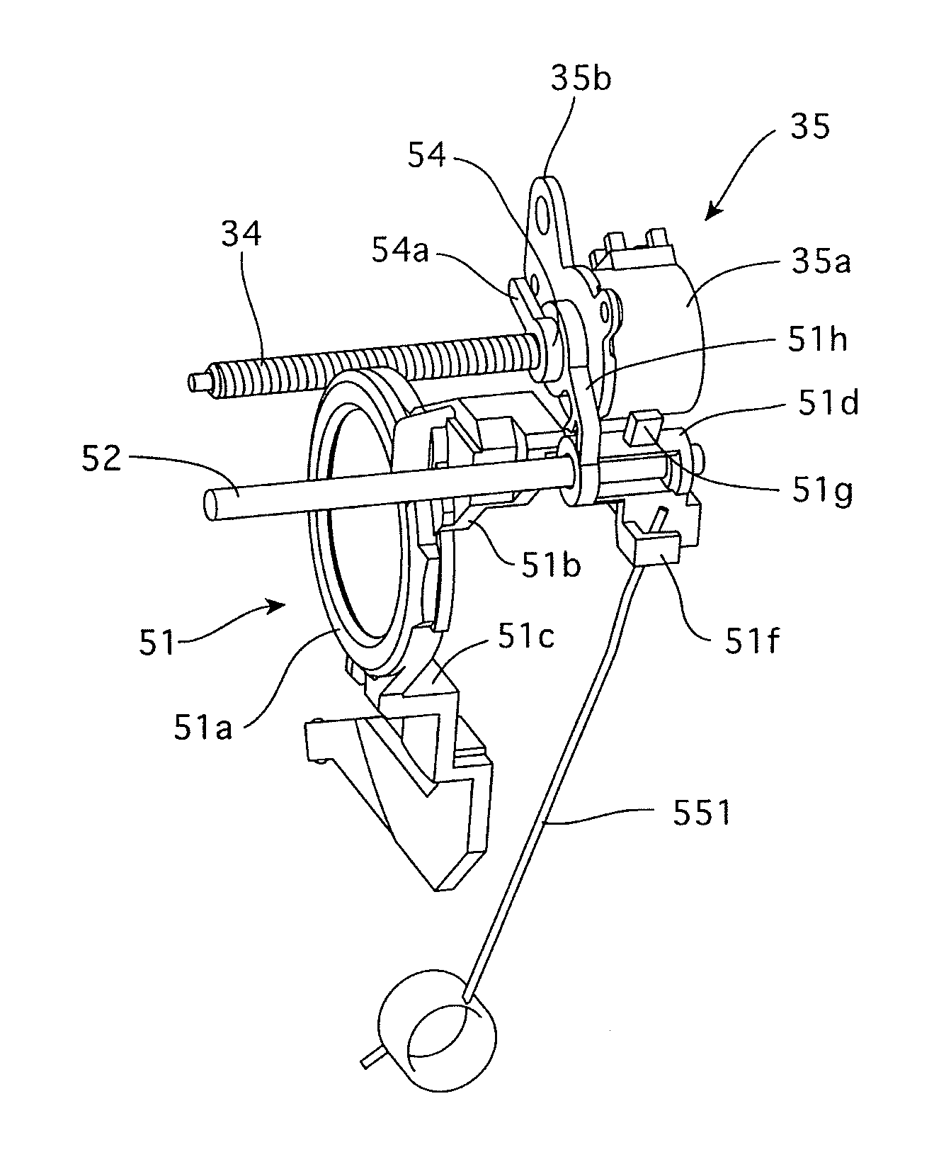
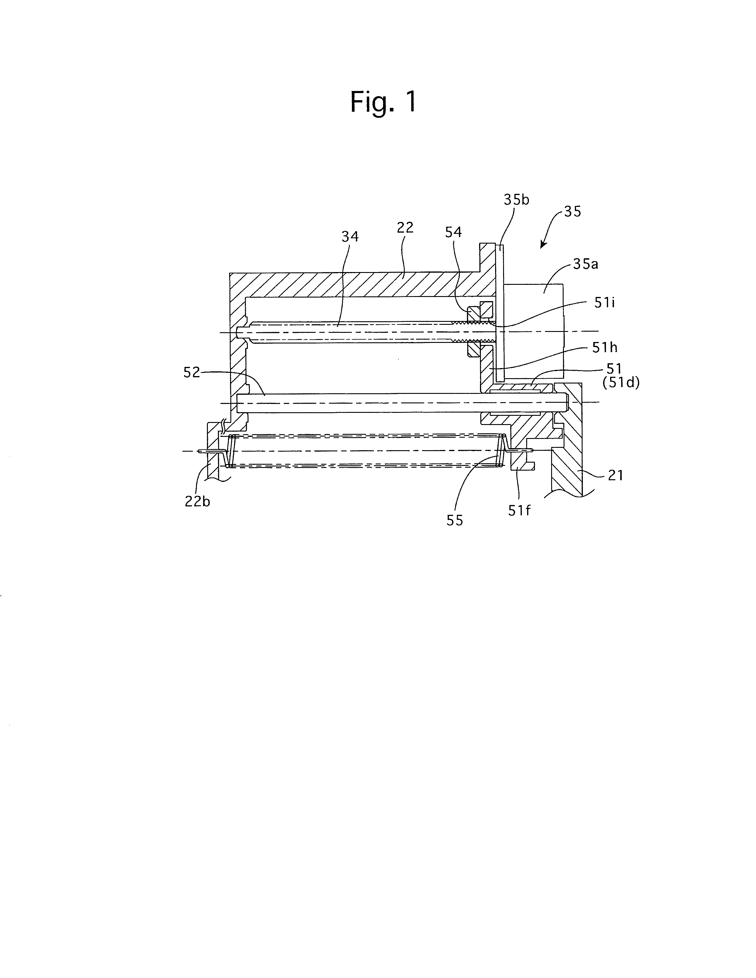
[0033]FIGS. 8 and 9 show the overall structure of a zoom lens barrel 1 that is equipped with a lens moving mechanism according to the present invention. FIGS. 1 and 4 show the lens moving mechanism. FIG. 8 shows the zoom lens barrel 1 in a lens barrel accommodated state (fully-retracted state), the upper half of the zoom lens barrel 1 in FIG. 9 shows a state of the zoom lens barrel 1 set at a wide-angle extremity, and the lower half of the zoom lens barrel 1 in FIG. 9 shows a state of the zoom lens barrel 1 set at a telephoto extremity.

[0034]The zoom lens barrel 1 is provided with a photographing optical system which includes a first lens group LG1, a second lens group LG2, a shutter (mechanical shutter) S that also serves as a diaphragm, a third lens group LG3, a fourth lens group LG4, an IR cut filter and a CCD image sensor (image-pickup device) 20, in that order from the object side (see FIG. 8). This photographing optical system is configured as a zoom optical system, in which t...
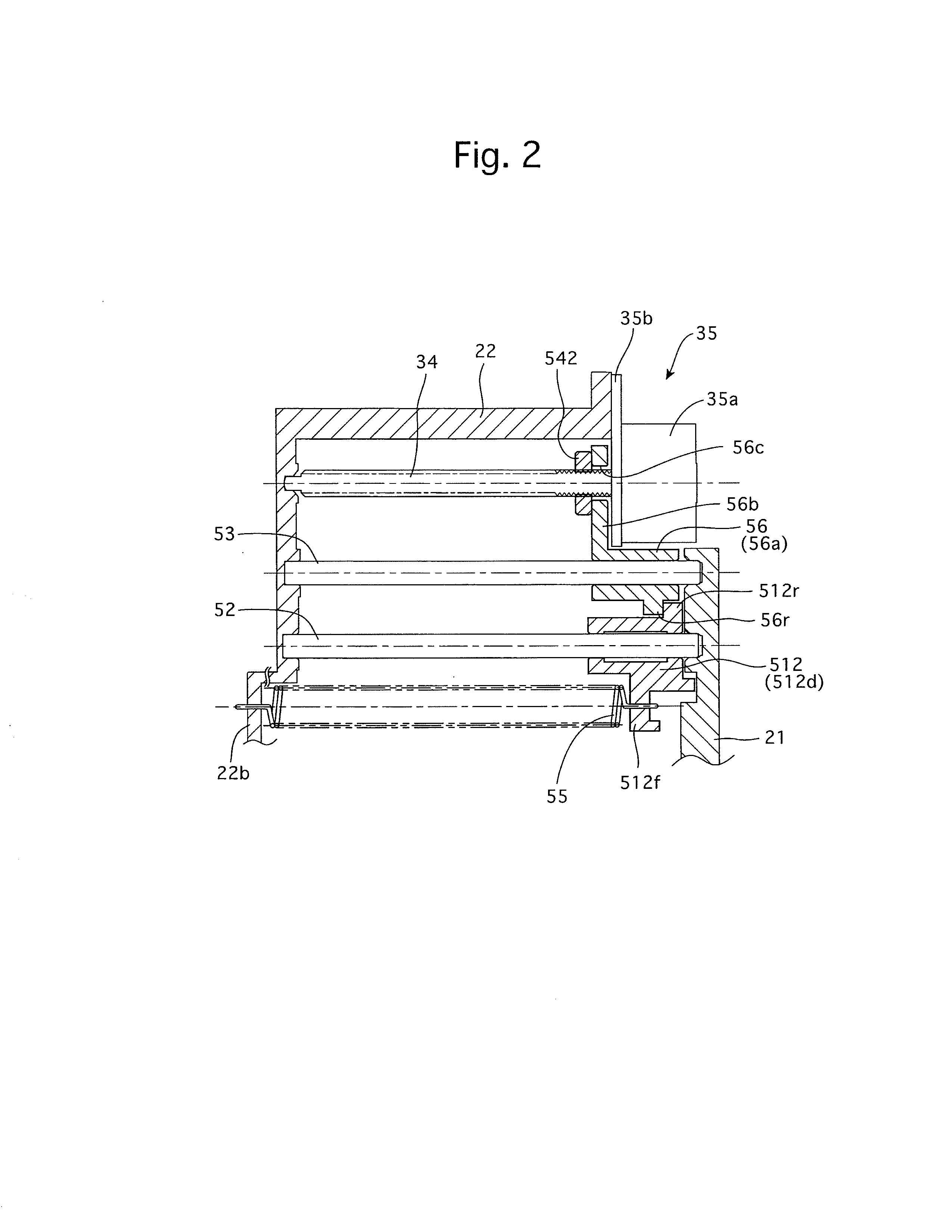
second embodiment

[0049]The fourth lens group frame 512 that holds the fourth lens group LG4 is provided with a central lens holding portion 512a and a pair of guide arm portions 512b and 512c which are formed to extend from the central lens holding portion 512a in substantially opposite radial directions with respect to the photographing optical axis O. The guide arm portion 512b is provided at the radially outer end thereof with a cylindrical guide portion (fit-on portion) 512d into which a fourth lens group guide shaft 52, which is fixed between the stationary barrel 22 and the lens barrel back plate 21, is inserted to be slidable relative to the cylindrical guide portion 512d. The radially outer end of the guide arm portion 512c is engaged into a groove, formed in the inner surface of the stationary barrel 22, to be slidable therealong. The fourth lens group frame 512 is provided with a spring hook 512f (see FIG. 2), and an end of an extension spring 55 is hooked on the spring hook 512f. The othe...


PUM


Abstract

A lens moving mechanism includes a guide shaft extending in an optical axis direction and a lens frame. The lens frame includes a transfer portion which follows movement of the nut member, which is screw-engaged with a lead screw of a motor. An effective length of the guide shaft is greater than that of the lead screw so that an end of the guide shaft and the motor overlap each other. Part of the fit-on portion of the lens frame is positioned where the end of the guide shaft and the motor overlap each other when the lens frame is at a lens-frame moving end, and is positioned to face the lead screw in a direction orthogonal to the optical axis when the lens frame is at the opposite lens-frame moving end.

Description

FIELD OF THE INVENTION[0001]The present invention relates to a lens moving mechanism which moves a lens forward and reverse by a motor-driven lead screw mechanism.DESCRIPTION OF THE RELATED ART[0002]As a mechanism which moves a lens group of a camera in an optical axis direction, a mechanism which biases a lens frame in an optical axis direction and presses and moves this lens frame against the biasing force by rotating a motor-driven lead screw via a lead nut member, which is screw-engaged with the lead screw with being prevented from rotating, is known in the art. This mechanism is disclosed in Japanese Unexamined Patent Publication No. 2009-192965.[0003]In this mechanism that is disclosed in the above-mentioned Japanese Unexamined Patent Publication No. 2009-192965, a spring is fitted on a guide shaft which guides the lens frame in the optical axis direction to bias a connecting portion of the lens frame, which is engaged with the guide shaft, in the optical axis direction.[0004]...

Claims


Application Information

Patent Timeline
Patent Type & Authority Applications(United States)
IPC IPC(8): G02B7/04
CPCG02B7/04G02B7/102
Inventor MIYA, KOTANOMURA, HIROSHI
Owner HOYA CORP
Why Eureka
Try Eureka