Lens Assembly

Active Publication Date: 2020-06-11
SINTAI OPTICAL SHENZHEN CO LTD +1
View PDF0 Cites 0 Cited by
  • Summary
  • Abstract
  • Description
  • Claims
  • Application Information

AI Technical Summary

Benefits of technology

The invention is a lens assembly that solves issues with being too long, heavy, and having low resolution. It has good optical performance. This means that the lens assembly is designed to have these properties, making it easier to use and better for producing high-quality images.

Problems solved by technology

However, the known lens assembly can't satisfy such requirements.

Method used


Image

  • Lens Assembly
  • Lens Assembly
  • Lens Assembly

Examples


first embodiment

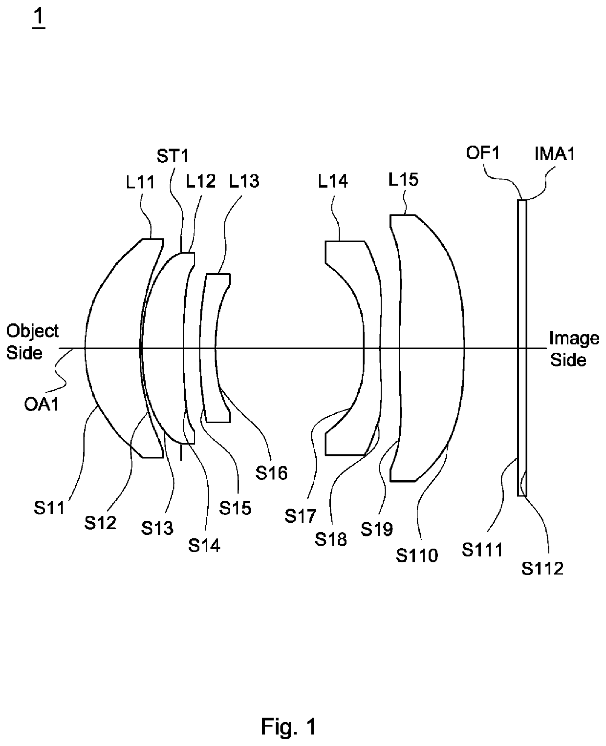
[0041]A detailed description of a lens assembly in accordance with the invention is as follows. Referring to FIG. 1, the lens assembly 1 includes a first lens L11, a stop ST1, a second lens L12, a third lens L13, a fourth lens L14, a fifth lens L15, and an optical filter OF1, all of which are arranged in order from an object side to an image side along an optical axis OA1. In operation, an image of light rays from the object side is formed at an image plane IMA1.

[0042]According to paragraphs [0026]-[0035], the second lens L12 is a meniscus lens, wherein the object side surface S13 is a convex surface and the image side surface S14 is a concave surface; the third lens L13 is a meniscus lens, wherein the object side surface S15 is a convex surface and the image side surface S16 is a concave surface; the fourth lens L14 is a biconcave lens, wherein the image side surface S18 is a concave surface; the fifth lens L15 is biconvex lens, wherein the object side surface S19 is a convex surfa...

second embodiment

[0053]Referring to FIG. 3, FIG. 3 is a lens layout diagram of a lens assembly in accordance with the invention. The lens assembly 2 includes a first lens L21, a stop ST2, a second lens L22, a third lens L23, a fourth lens L24, a fifth lens L25, and an optical filter OF2, all of which are arranged in order from an object side to an image side along an optical axis OA2. In operation, an image of light rays from the object side is formed at an image plane IMA2.

[0054]According to paragraphs [0026]-[0035], the surface profiles of the second lens L22, the third lens L23, the fourth lens L24, and the fifth lens L25 approximate to that of the second lens L12, the third lens L13, the fourth lens L14, and the fifth lens L15 of the lens assembly 1 of the first embodiment respectively, and is not described here again; and both of the object side surface S211 and image side surface S212 of the optical filter OF2 are plane surfaces.

[0055]With the above design of the lenses and stop ST2 and at lea...

third embodiment

[0065]Referring to FIG. 5, FIG. 5 is a lens layout diagram of a lens assembly in accordance with the invention. The lens assembly 3 includes a first lens L31, a stop ST3, a second lens L32, a third lens L33, a fourth lens L34, a fifth lens L35, and an optical filter OF3, all of which are arranged in order from an object side to an image side along an optical axis OA3. In operation, an image of light rays from the object side is formed at an image plane IMA3.

[0066]According to paragraphs [0026]-[0035], the surface profiles of the second lens L32, the third lens L33, the fourth lens L34, and the fifth lens L35 approximate to that of the second lens L12, the third lens L13, the fourth lens L14, and the fifth lens L15 of the lens assembly 1 of the first embodiment respectively, and is not described here again; and both of the object side surface S311 and image side surface S312 of the optical filter OF3 are plane surfaces.

[0067]With the above design of the lenses and stop ST3 and at lea...


PUM


Abstract

A lens assembly includes a first lens, a second lens, a third lens, a fourth lens, and a fifth lens. The first lens is with positive refractive power and includes a convex surface facing an object side and a concave surface facing an image side. The second lens is with positive refractive power. The third lens is with negative refractive power and includes a convex surface facing the object side. The fourth lens is with negative refractive power and includes a concave surface facing the object side. The fifth lens is with positive refractive power and includes a convex surface facing the image side.

Description

BACKGROUND OF THE INVENTIONField of the Invention[0001]The invention relates to a lens assembly.Description of the Related Art[0002]The current development trend of a lens assembly is toward miniaturization. Additionally, the lens assembly is developed to have light weight and high resolution capability in accordance with different application requirements. However, the known lens assembly can't satisfy such requirements. Therefore, the lens assembly needs a new structure in order to meet the requirements of miniaturization, light weight, and high resolution at the same time.BRIEF SUMMARY OF THE INVENTION[0003]The invention provides a lens assembly to solve the above problems. The lens assembly of the invention is provided with characteristics of a shortened total lens length, a lighter weight, a higher resolution, and still has a good optical performance.[0004]The lens assembly in accordance with an exemplary embodiment of the invention includes a first lens, a second lens, a third...

Claims


Application Information

Patent Timeline
IPC IPC(8): G02B13/00G02B9/60
CPCG02B13/0045G02B9/60G02B13/18
Inventor CHANG, HSI-LINGWU, GUO-YANG
Owner SINTAI OPTICAL SHENZHEN CO LTD
Why Eureka
Try Eureka