Lens Assembly

a technology of lens and assembly, applied in the field of lenses, can solve the problems that smartphones cannot be equipped with traditional optical zoom lenses, thin and light smartphones, etc., and achieve the effects of reducing the total lens length, improving resolution, and good optical performan

Pending Publication Date: 2022-01-27
SINTAI OPTICAL SHENZHEN CO LTD +1
View PDF0 Cites 0 Cited by
  • Summary
  • Abstract
  • Description
  • Claims
  • Application Information

AI Technical Summary

Benefits of technology

[0003]The invention provides a lens assembly to solve the above problems. The lens assembly of the invention is provided with characteristics of a decreased total lens length, an increased resolution, an optical zoom function, and still has a good optical performance. In addition, the purpose of the present invention is to provide the lens assembly having a zoom control method at the same time. A clear image can be obtained regardless of whether it is at a high zoom ratio or at a low zoom ratio.

Problems solved by technology

Today's thin and light smartphone cannot be equipped with traditional optical zoom lens because the total length of the optical zoom lens is longer and the total length becomes longer as the zoom ratio increases.

Method used


Image

  • Lens Assembly
  • Lens Assembly
  • Lens Assembly

Examples


first embodiment

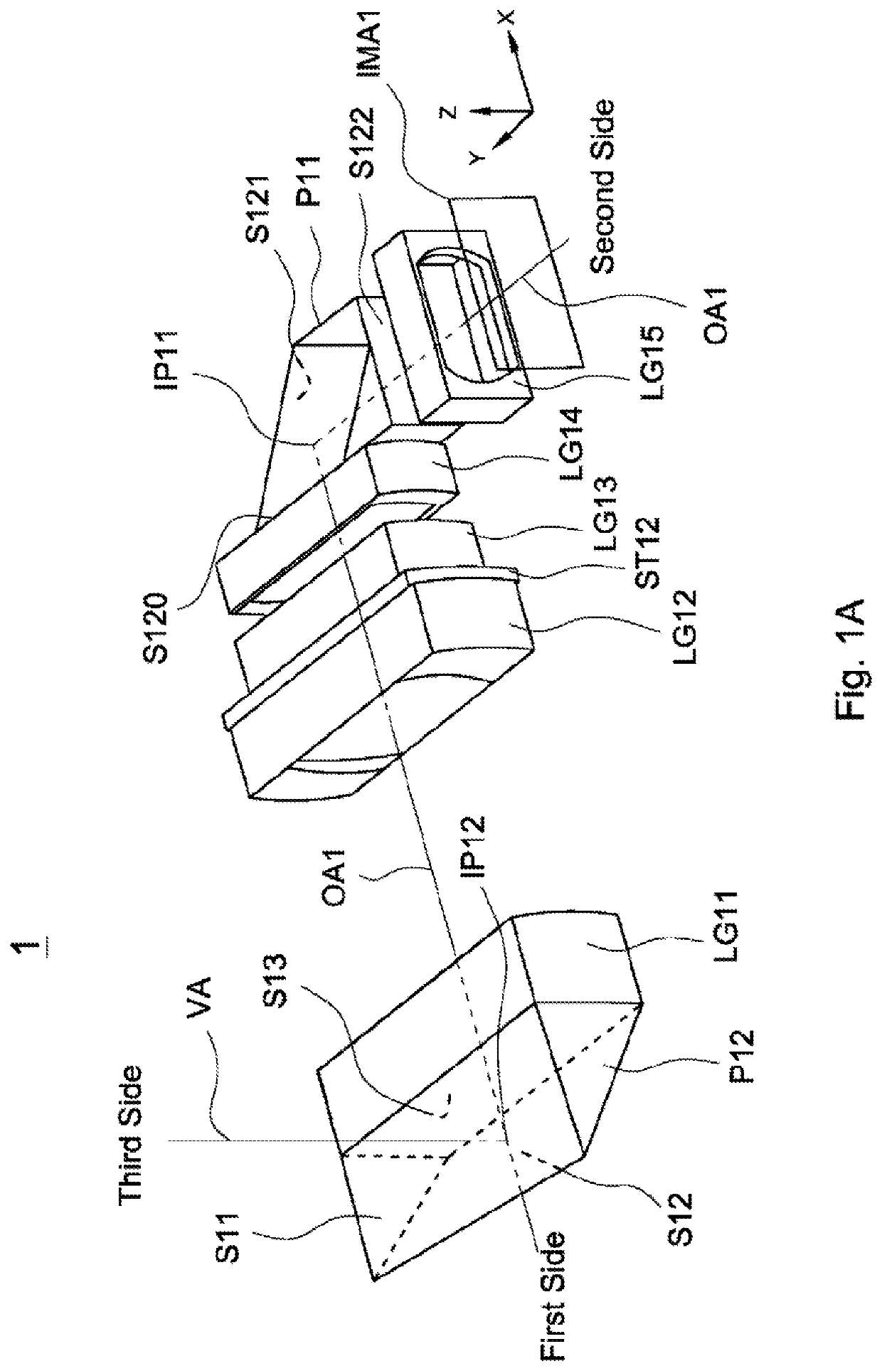
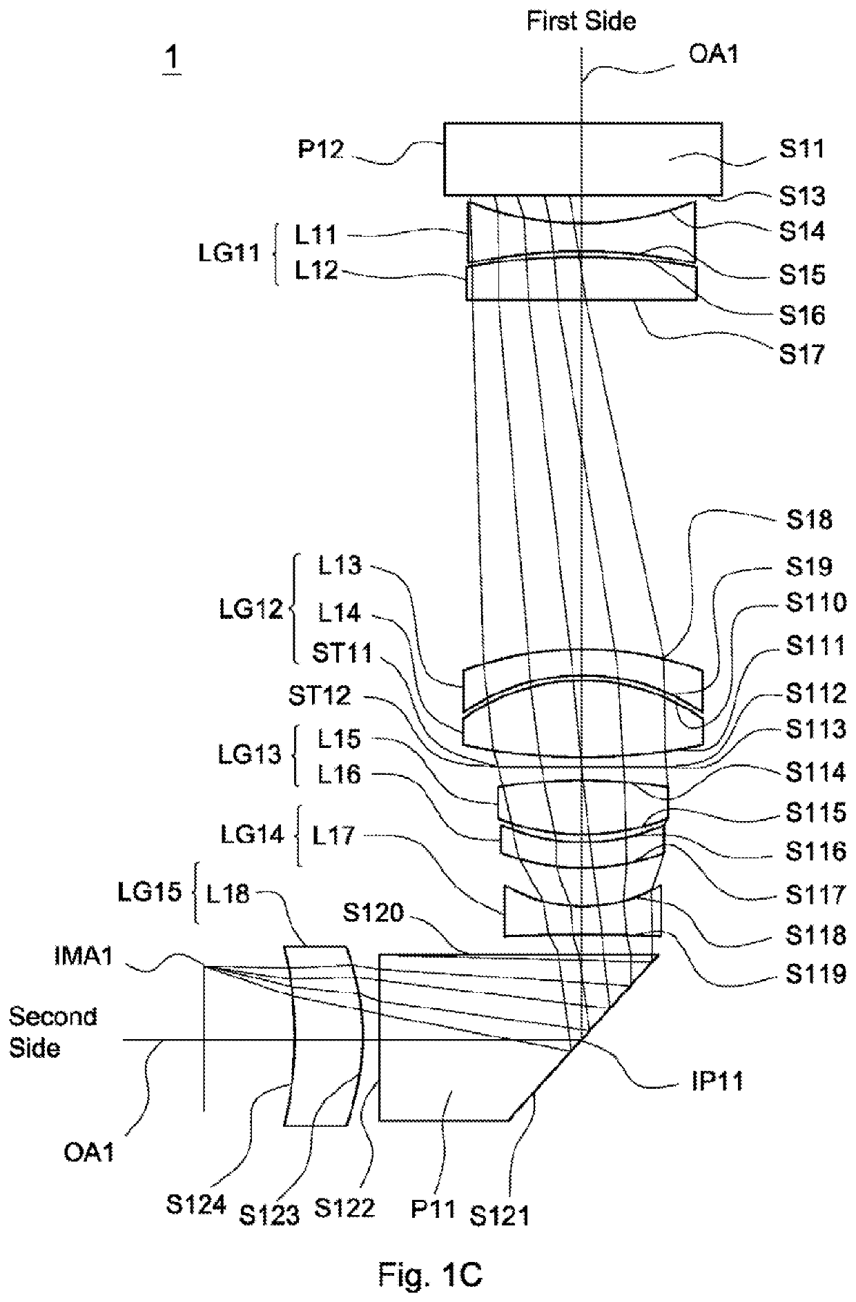
[0039]A detailed description of a lens assembly in accordance with the invention is as follows. Referring to FIG. 1A, FIG. 1B, FIG. 1D, and FIG. 1G. The lens assembly 1 includes a second reflective element P12, a first lens group LG11, a second lens group LG12, a second stop ST12, a third lens group LG13, a fourth lens group LG14, a first reflective element P11, and a fifth lens group. LG15. The second reflective element P12 is a prism and includes a second incident surface S11, a second reflective surface S12, and a second exit surface S13. The second incident surface S11 faces the third side along the vertical axis VA. The second reflective surface S12 faces the second side along the axis OA1. The second exit surface S13 faces the second side along the axis OA1. The second incident surface S11 and the second exit surface S13 are perpendicular to each other. The second reflective element P12 can also be a reflective mirror. The second reflective element P12 can also only include on...

fourth embodiment

[0081]The fifth lens group LG55 can move to the second side or the point IP51 along the axis OA5 for auto focus. In operation, the light path of the tight from the third side (not shown) is the same as that of in the fourth embodiment, and will not be described here again.

[0082]In addition, the lens assembly 5 satisfies at least one of the conditions (1)-(11), wherein the definition of each parameter is the same as that of in the first embodiment, and will not be described here again. When any one of the above conditions (1)-(11) is satisfied, the refractive power of the lens assembly 5 can be effectively distributed to reduce the sensitivity of the lens assembly 5. With the above design of the lenses, stop ST51, reflective element P52, reflective element P51, beam splitter BS5, and at least any one of the conditions (1)-(11) satisfied, the lens assembly 5 can have an effectively decreased total lens length, an effective increased resolution, an effective corrected aberration, and t...

sixth embodiment

[0094]The definition of aspheric surface sag z of each aspheric lens in table 10 is the same as that of in Table 1, and is not described here again. In the sixth embodiment, the conic constant k and the aspheric coefficients A, B, C, D, E, F, G of each aspheric lens are shown in Table 11.

TABLE 11SurfaceNumberkABCDEFGS61   0.605534−8.2521E−06−4.2900E−06  1.1144E−07  1.6441E−08  1.9782E−11−4.1374E−11  8.8215E−13S62 −0.05297−9.8776E−06  3.9308E−07−1.1968E−08  5.7062E−09  1.5351E−10−5.6251E−12  3.4005E−13S63   0.069091−5.1377E−07−2.7525E−06−8.2468E−08−7.3903E−09−9.2040E−11  4.4839E−12  3.3640E−13S64   0.180518  2.0777E−06−3.2906E−06−2.7644E−07  4.1752E−10  1.3338E−10−4.2991E−12−1.8689E−13S69 −0.46605  2.3596E−05  2.0210E−06  2.7809E−07  1.8273E−08  1.0821E−09  4.9151E−11−2.2898E−11S610 −2.79878  7.3967E−06  2.0203E−06  7.9069E−08  1.2561E−08  1.2412E−09  2.8550E−11−1.5229E−11S611−49.0118−1.1863E−04−7.7431E−06−2.1814E−07−3.4040E−08−8.2242E−09  1.8031E−10  2.7308E−11S612   2.164263−1.0333...


PUM


Abstract

A lens assembly includes a first lens group, a second lens group, a third lens group, a fourth lens group, and a fifth lens group, all of which are arranged in order from a first side to a second side along an axis. The first lens group is with negative refractive power. The second lens group is with positive refractive power. The third lens group is with refractive power. The fourth lens group is with refractive power. The fifth lens group is with refractive power. The lens assembly further includes a first reflective element disposed between the first lens group and the fifth lens group, wherein the first reflective element includes a first reflective surface.

Description

BACKGROUND OF THE INVENTIONField of the Invention[0001]The invention relates to a lens assembly.DESCRIPTION OF THE RELATED ART[0002]The development of optical zoom technology has been quite mature. A large number of optical zoom lenses are used in digital single-lens reflex camera with interchangeable lens and digital non-interchangeable lens camera. Today's thin and light smartphone cannot be equipped with traditional optical zoom lens because the total length of the optical zoom lens is longer and the total length becomes longer as the zoom ratio increases. Therefore, a lens assembly needs a new structure having miniaturization, high resolution, and optical zoom at the same time, in order to meet the requirements of smart phone for optical zoom function.BRIEF SUMMARY OF THE INVENTION[0003]The invention provides a lens assembly to solve the above problems. The lens assembly of the invention is provided with characteristics of a decreased total lens length, an increased resolution, ...

Claims


Application Information

Patent Timeline
Patent Type & Authority Applications(United States)
IPC IPC(8): G02B15/14G02B9/64
CPCG02B15/1455G02B27/0025G02B9/64G02B13/0065G02B13/009G03B13/36G03B30/00G02B13/0045G02B13/18G02B27/0012
Inventor CHANG, HSI-LINGYAO, CHUN-YANGTSENG, MING-HUANGCHEN, CHIEN-HUNG
Owner SINTAI OPTICAL SHENZHEN CO LTD
Why Eureka
Try Eureka