
Portable electronic device and its optical imaging lens

An optical imaging lens and imaging technology, applied in optics, focusing devices, optical components, etc., can solve problems such as unfavorable thin design, achieve good optical performance, and shorten the length of the lens

Active Publication Date: 2016-05-11
GENIUS ELECTRONICS OPTICAL XIAMEN
View PDF9 Cites 0 Cited by
  • Summary
  • Abstract
  • Description
  • Claims
  • Application Information

AI Technical Summary

Problems solved by technology

[0004] In U.S. Patent Nos. US7920340, US7660049 and US7848032, the disclosed optical imaging lenses all have a four-piece lens structure, and the distance from the object side of the first lens to the imaging surface on the optical axis is greater than 7mm, which is not conducive to mobile phones and digital cameras. Thin design of portable electronic products such as

Method used


Image

  • Portable electronic device and its optical imaging lens
  • Portable electronic device and its optical imaging lens
  • Portable electronic device and its optical imaging lens

Examples


Embodiment Construction

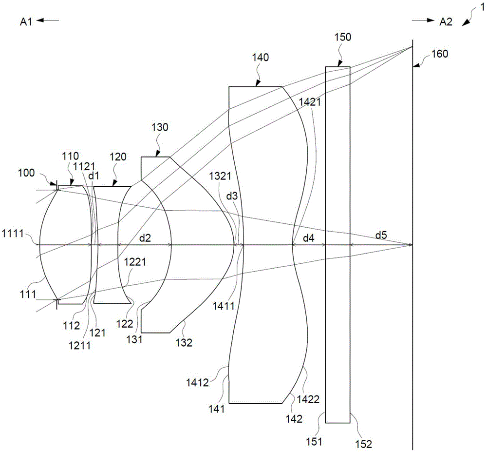
[0114] To further illustrate various embodiments, the present invention provides drawings. These drawings are a part of the disclosure content of the present invention, which are mainly used to illustrate the embodiments, and can cooperate with the relevant descriptions in the manual to explain the operating principles of the embodiments. With reference to these contents, those skilled in the art should understand other possible implementations and advantages of the present invention. Components in the figures are not drawn to scale, and similar component symbols are generally used to denote similar components.

[0115] The term "a lens has positive refractive power (or negative refractive power)" mentioned in this specification means that the lens has positive refractive power (or negative refractive power) in the area near the optical axis. "The object side (or image side) of a lens includes a convex surface (or concave surface) located in a certain area" means that the are...


PUM


Abstract

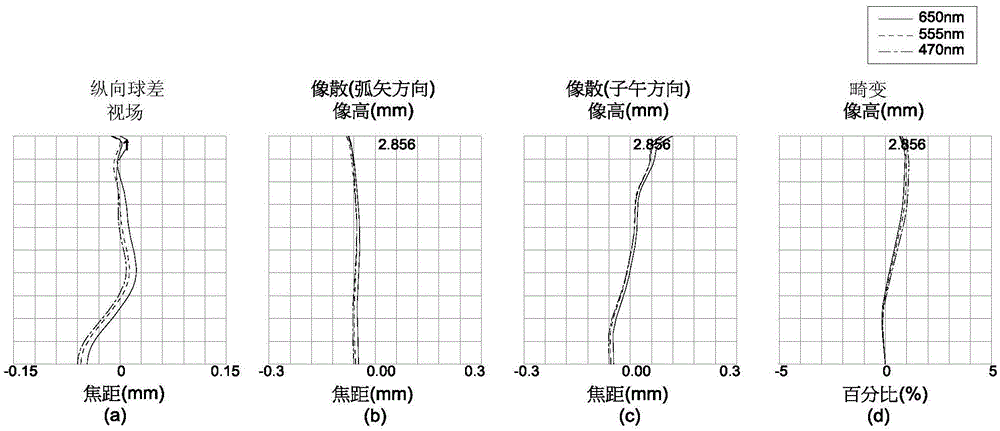
The invention relates to an optical imaging lens and an electronic device using the optical imaging lens. An optical imaging lens of the present invention includes four lenses in sequence, the object side of the first lens has a convex portion located near the optical axis, and the image side of the first lens has a convex portion located near the optical axis. The second lens has a negative refractive power, the object side of the second lens has a concave surface located in the vicinity of the circumference, and the image side of the second lens has a concave surface located in the vicinity of the circumference. The object side of the third lens is a concave surface, and the image side of the third lens has a convex portion located near the optical axis. The object side of the fourth lens has a convex portion located near the circumference and is made of plastic. The electronic device of the present invention includes a casing, an image module, the above-mentioned optical imaging lens, lens barrel, module rear seat unit and image sensor. The present invention shortens the length of the lens under the condition of maintaining good optical performance by controlling the concave-convex surface arrangement of each lens.

Description

technical field [0001] The present invention is related to a portable electronic device and its optical imaging lens, and especially related to a portable electronic device using a four-piece lens and its optical imaging lens. Background technique [0002] In recent years, the popularization of mobile phones and digital cameras has led to the vigorous development of photographic modules including optical imaging lenses, lens barrels, and image sensors. The thinner and lighter mobile phones and digital cameras have also increased the demand for miniaturization of photographic modules. With the technological progress and size reduction of the photosensitive coupling device (Charge Coupled Device, referred to as CCD) or complementary metal oxide semiconductor device (Complementary Metal-Oxide Semiconductor, referred to as CMOS), the optical imaging lens installed in the camera module also needs to be reduced in size, but the optical imaging lens Good optical performance is also...

Claims


Application Information

Patent Timeline
IPC IPC(8): G02B13/00G02B13/18
CPCG02B13/004G03B13/32
Inventor 陈锋叶龙陈雁斌
Owner GENIUS ELECTRONICS OPTICAL XIAMEN
Learn More