Locking and folding assembly for attachment to a bucket or other container

a technology for buckets and containers, applied in the field of leg assemblies, can solve the problems of reducing the likelihood of a re-use, affecting the safety of the re-use container, and bending down for re-use can become tiresome, etc., and achieves the effects of reducing the likelihood of re-use, convenient portability, and simple operation

Active Publication Date: 2017-11-09
ABTEC
View PDF2 Cites 0 Cited by
  • Summary
  • Abstract
  • Description
  • Claims
  • Application Information

AI Technical Summary

Benefits of technology

[0008]The leg assembly of the present provides an inexpensive, simple to operate, easily portable, and reliable way to securely elevate a bucket from the ground or a floor, while also providing a way to compactly fold the legs during storage of the bucket with the attached legs or when it is desired to place the bottom of the bucket directly on the ground or a floor. By providing that the legs can be locked in the down position, the likelihood is substantially reduced that the legs will collapse should the bucket be jarred. Additionally, by using an adhesive layer to attach the leg assembly to the bucket rather than nuts and bolts or a frame around the bucket, assembly is easy, and the integrity of the bucket will not be compromised. Because any number of leg assemblies can be used, the size, shape and weight of the bucket or container to be supported by the leg assembly of the present invention is not limited.
[0009]Furthermore, when the leg is locked into the down position, the leg is angled away from the direct force of the bucket on the flange. This directs the force to the flange and forces the edge of the bracket against the bucket, thus assisting in maintaining the bracket to the bucket.

Problems solved by technology

If the items are repeatedly retrieved, such bending down for retrieval can become tiresome.
Also, if paint or a cleaning liquid is placed in the bucket, the liquid could spoil the support.
These features add cost, add weight, and may damage the bucket being supported.
Accordingly, these devices have not met commercial success, despite the fact that buckets are ubiquitous in many industries, and that such a device would benefit all users of buckets.

Method used


Image

  • Locking and folding assembly for attachment to a bucket or other container
  • Locking and folding assembly for attachment to a bucket or other container
  • Locking and folding assembly for attachment to a bucket or other container

Examples


Embodiment Construction

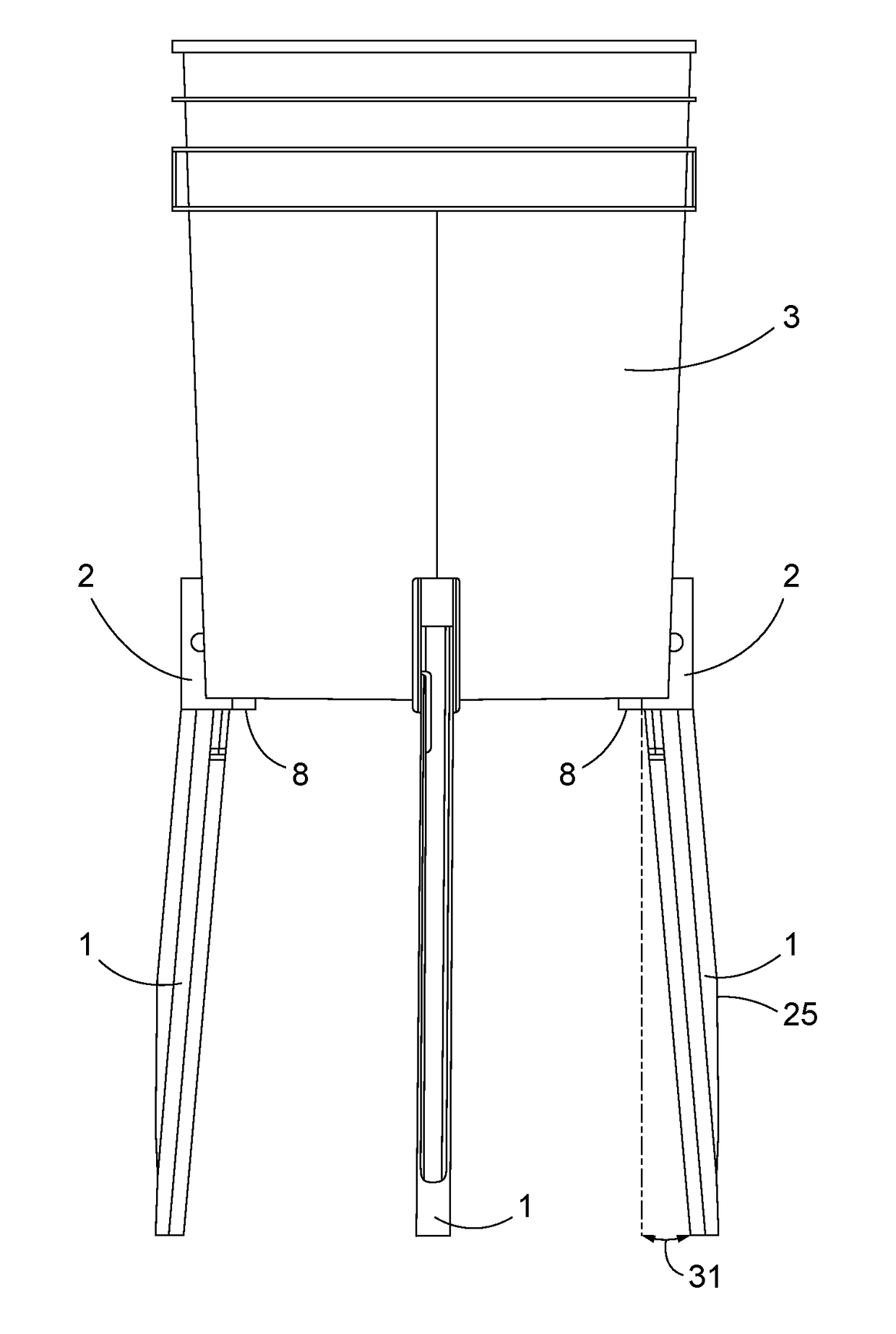
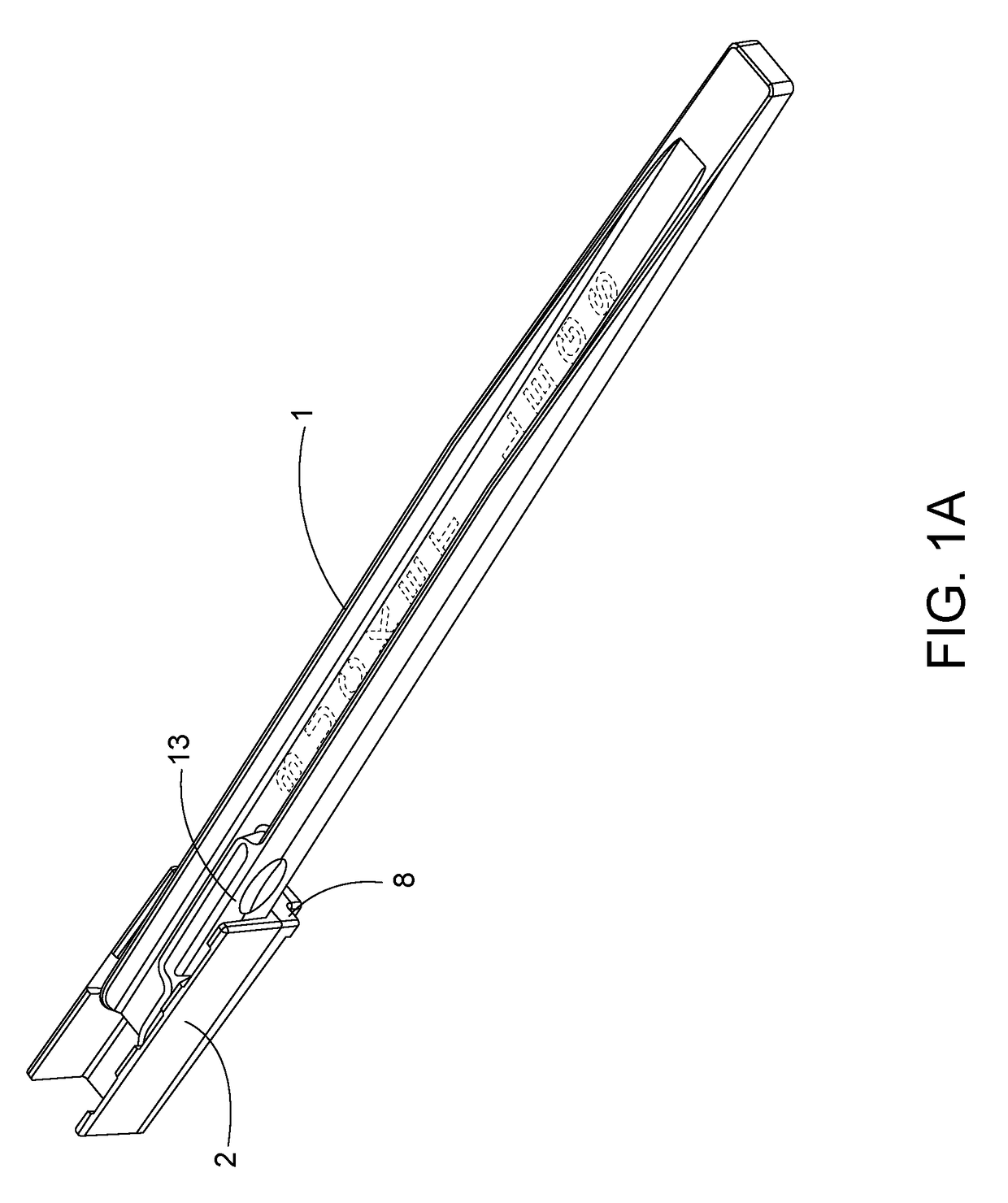
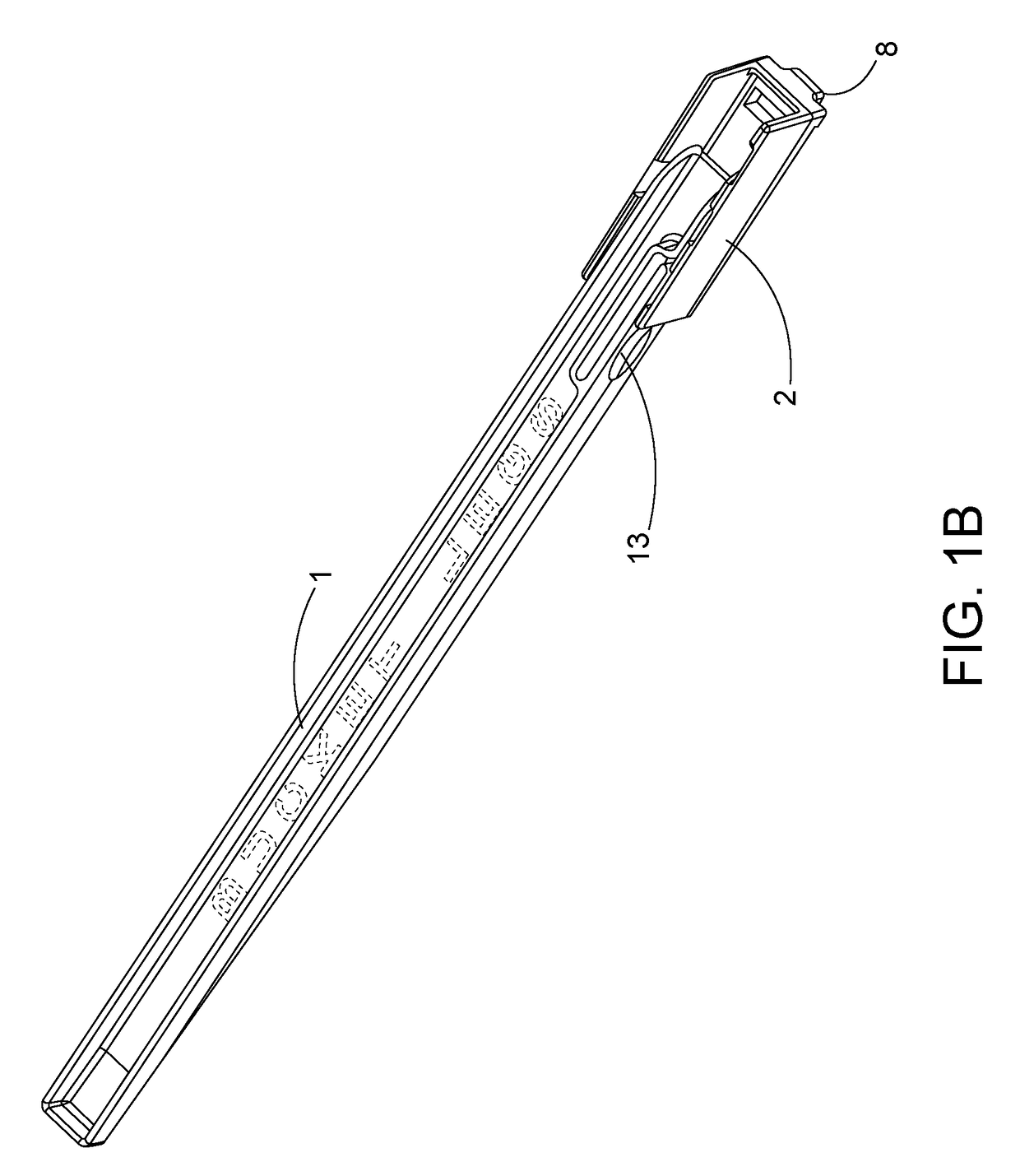
[0022]Referring to FIG. 1A, the leg assembly has two parts, an elongated leg 1 and a substantially U shaped mounting bracket 2. In FIG. 1A, the leg 1, which is rotatably mounted in bracket 2, is shown in the down-locked position, and in FIG. 6, the leg assembly is shown attached to a bucket 3 with the leg 1 in bracket 2 in the down locked position. In FIG. 1B, the leg 1 is shown in the up folded position, and in FIG. 7, the leg assembly is shown attached to a bucket 3 with the leg 1 in bracket 2 in the up folded position. The length of leg 1 is selected to be appropriate for the particular intended use. Thus, if the intended use requires that the bottom of the bucket 3 be 15″ above the ground or floor, leg 1 is about 15″ in length. For other bucket heights, the length of leg 1 is appropriately sized in length, or the leg may be adjustable in length to allow for adjustment based on the needs of the particular user.

[0023]As is shown in FIGS. 2A and 2B, the leg comprises a bracket end ...


PUM


Abstract

A leg assembly capable of easy attachment to a container, having an elongated leg and a bracket, where the bracket contains a mounting pocket, two slots, substantially parallel to one another, and wherein at one end of the bracket there is disposed an L-shaped flange, and wherein the elongated leg contains a pin on each side of an end of the leg, and mounted so that the leg may rotate in the mounting pocket of the bracket, and wherein the leg has an outward protruding pin sized and shaped to fit into the two parallel recesses, and wherein the pin is formed on a flexible arm on the leg capable of being depressed to move the pin inward.

Description

CROSS REFERENCE TO RELATED APPLICATION[0001]This application claims the benefit of U.S. Provisional Application Ser. No. 62 / 333,359, filed May 9, 2016, the disclosure content of which is hereby incorporated by reference in its entirety.FIELD OF THE INVENTION[0002]This invention relates to a leg assembly which is capable of easy, secure attachment to a bucket or other container and which is capable of assuming a down-locked position, in which the leg is extended downward to support a bottom of a bucket above and off the ground or floor, and an up folded position, in which the leg is folded upward against a side of the bucket so that the bottom of the bucket or the bottom of the leg assembly can sit directly on the ground or floor.BACKGROUND OF THE INVENTION[0003]Although buckets and pails are widely available inexpensively from hardware stores, in use, these buckets and pails are placed on the ground or floor. Thus, if a user wants to retrieve an item in the bottom of the bucket or p...

Claims


Application Information

Patent Timeline
Patent Type & Authority Applications(United States)
IPC IPC(8): B65D25/24B44D3/14B65D25/20B65F1/14E06C7/44
CPCB65D25/24B65D25/20B65F1/14B62B2202/028B44D3/14E06C7/44
Inventor SINCLAIR, WILLIAM S.
Owner ABTEC
Why Eureka
Try Eureka