Electric gear pump

a gear pump and electric technology, applied in the direction of rotary/oscillating piston pump components, machines/engines, liquid fuel engines, etc., can solve the problems of difficult placement of magnets inside the internal spur rotor as described above, and the internal surface of mechanical machining of the external surface of the rotor does not always achieve the circularity tolerance required. , to achieve the effect of improving the circularity and simple and quick positioning of magnets

Inactive Publication Date: 2019-10-24
ROBERT BOSCH GMBH
View PDF0 Cites 0 Cited by
  • Summary
  • Abstract
  • Description
  • Claims
  • Application Information

AI Technical Summary

Benefits of technology

[0029]Advantageously, according to this embodiment, positioning the magnet is simple and quick since they lie along the whole periphery of the internal spur rotor. Moreover, according to this embodiment, there is a constant dista

Problems solved by technology

Although gerotor electric gear pumps are widely used, the current versions of these pumps have a number of drawbacks.
In particular, placing the magnets inside the internal spur rotor as described above is a difficult, expensive process.
Mo

Method used


Image

  • Electric gear pump
  • Electric gear pump

Examples


first embodiment

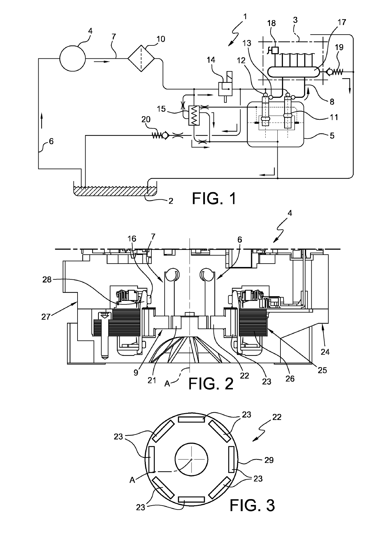
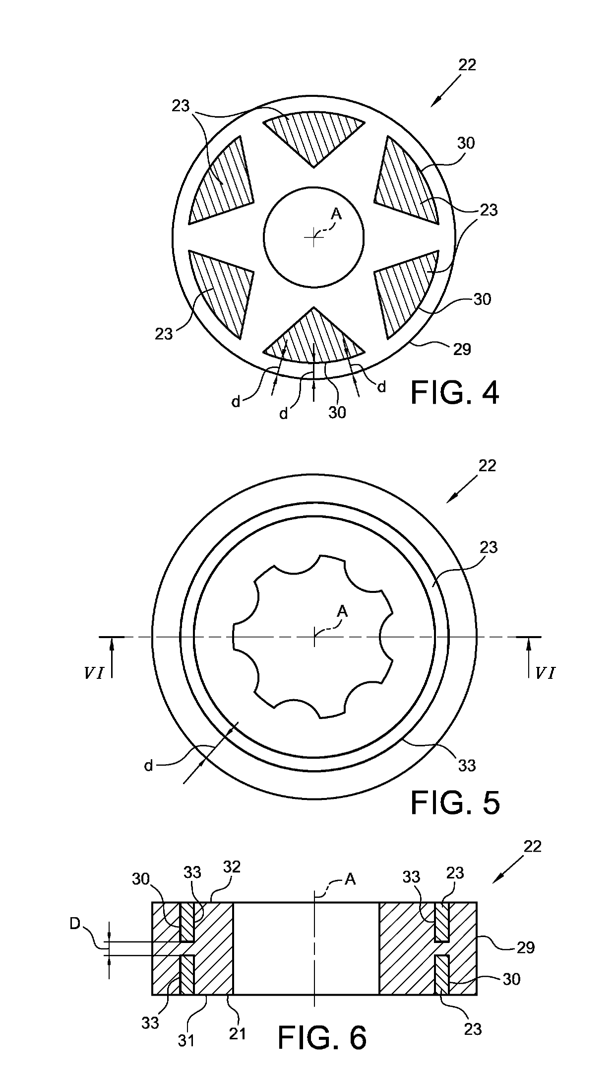
[0054]FIG. 4 is a schematic view of an internal spur rotor 22 according to the invention in which homogeneous distribution of material, or a constant distance d measured radially, is guaranteed between the magnets 23 and the corresponding portions of the external surface 29 of the internal spur rotor 22. This technical effect is achieved in the embodiment of FIG. 4 by virtue of a plurality of magnets 23 arranged along the circular periphery of the internal spur rotor 22 in which said magnets have an external surface 30 which, viewed from a plane orthogonal to the axis A, coincides with an arc of a circle centred on said axis A.

[0055]Such magnets may be provided embedded in the internal spur rotor 22 or inserted in special seats made on the lower and / or upper surface of the internal spur rotor 22. For the sake of clarity in FIG. 4, the internal spurs of the rotor 22 have not been shown.

second embodiment

[0056]FIG. 5 is a schematic view of an internal spur rotor 22 according to the invention in which homogeneous distribution of material, or a constant radial distance d, is guaranteed between the magnets 23 and the external surface 29 of the internal spur rotor 22. According to this embodiment, the magnets 23 are made in the form of a ring concentric with the axis A so as to guarantee along the internal periphery of the internal spur rotor 22 a homogeneous distribution of material, or a constant radial distance d, between the magnets 23 and the external surface 29 of the rotor.

[0057]FIG. 6 is a view in section of the internal spur rotor of FIG. 5 along the section line VI-VI. As can be seen, according to this embodiment, the internal spur rotor 22 comprises a first annular seat 33 made on the upper surface 32 and a first annular seat 33 made on the lower surface 31, in which said seats 33 are aligned in the axial direction A.

[0058]The distance between the seats in the axial direction...


PUM


Abstract

An electric gear pump comprising a gerotor that may rotate about an axis of rotation A, comprising an external spur rotor and an internal spur rotor arranged outside the external spur rotor; a stator having electrical windings arranged outside the internal spur rotor; at least one magnet at least partially housed in the internal spur rotor in such a way as to cause the gerotor to rotate when the electrical windings of the stator are supplied with current; in which the internal spur rotor comprises a cylindrical external surface centred on the axis of rotation A; the magnet comprises an external surface separated from the external surface of the internal spur rotor; the external surface of the magnet is shaped in such a way as to define a constant radial distance d between the magnet and the corresponding portion of the external surface of the internal spur rotor.

Description

BACKGROUND OF THE INVENTION[0001]The present invention relates to an electric gear pump. In particular, the present invention relates to a gerotor electric gear pump.[0002]The present invention also relates to a pump assembly comprising, in series:[0003]a low-pressure pump (the abovementioned gerotor electric gear pump) for drawing fuel, preferably diesel, and for initial compression of the fuel; and[0004]a high-pressure pump, preferably with pumping pistons, for further compression of the fuel and for supplying the fuel at high pressure to an internal combustion engine.[0005]The use of systems for supplying fuel, in particular diesel, to an internal combustion engine, which comprise a high-pressure pump for supplying the internal combustion engine, and a low-pressure pump for supplying fuel to the high-pressure pump, is already known. The high-pressure pump comprises at least one pumping piston moved by a shaft and housed in a cylinder supplied with fuel at low pressure. At least t...

Claims


Application Information

Patent Timeline
IPC IPC(8): F04C15/00F04C2/10
CPCF04C15/008F04C2/102F04C11/008F04C2210/203F04C2240/40F05B2210/11
Inventor MEDORO, NELLO
Owner ROBERT BOSCH GMBH
Why Eureka
Try Eureka