Multi-layer and multi-element monolithic surface mount fuse and method of making the same

a monolithic, surface mount technology, applied in the direction of electric switches, thermally actuated switches, electric apparatus, etc., can solve the problems of overload current flow, limitation of amperage rating, and numerous limitations of conventional surface mount chip fuses

Inactive Publication Date: 2000-03-07
AEM COMPONENTS
View PDF29 Cites 77 Cited by
  • Summary
  • Abstract
  • Description
  • Claims
  • Application Information

AI Technical Summary

Problems solved by technology

Short circuit conditions can occur in filter capacitors, supply lines or output loads which cause overload current flow.
Conventional surface mount chip fuses have numerous limitations.
The most notable limitation is amperage rating.
One reason for the amperage limitations of traditional chip fuses is related to the fusing element employed by these devices.
Fuses constructed in this manner are limited to lower amperage and voltage ratings (less than 5.0 amps and 36 VDC) due to their limited ability to suppress arcs which may occur during the clearing action when an overload current is present.
If the fuse element material protrudes from the surrounding substrate layers, the fuse material may continue to allow large amounts of current to pass and not effectively open the circuit.
The larger mass of element material utilized in the higher amperage devices often results in an increased probability that the surrounding arc suppressive layer will become saturated with the fusing material during a clearing action which can lead to catastrophic failure (e.g., a fuse which does not properly open a given circuit).

Method used


Image

  • Multi-layer and multi-element monolithic surface mount fuse and method of making the same
  • Multi-layer and multi-element monolithic surface mount fuse and method of making the same
  • Multi-layer and multi-element monolithic surface mount fuse and method of making the same

Examples


second embodiment

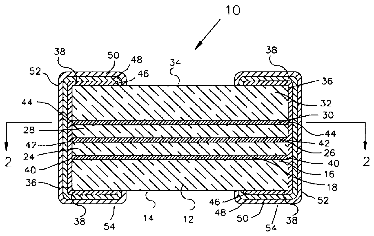
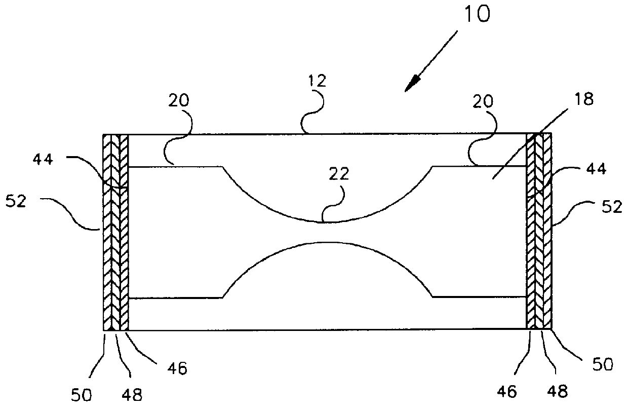
An alternative structure of the fusible element is shown in FIG. 4 and is substantially similar to the structure shown in FIG. 2 except that the neck-down portion 22 is formed of a different material than the end portions 20. Specifically. the end portions 20 are made of a low cost material such as silver, copper, aluminum, palladium and other noble metals (alone or in combination). Increased thermal cycling is achievable because the superior mechanical properties of the ceramic / glass composite is by nature very stable in a wide variety of environments. Improved soldering heat resistance survivability is also a function of the nature of the ceramic / glass composite material utilized (as compared to many surface mount fuses constructed with polymer based bodies). Increased breaking capacity is primarily a function to the multiple low mass elements utilized. Only the neck-down portion 22 is formed of the more expensive gold material. This allows the fusible elements to be manufactured ...


PUM

PropertyMeasurementUnit
lengthaaaaaaaaaa
lengthaaaaaaaaaa
thicknessaaaaaaaaaa

Abstract

A surface mount fuse includes a plurality of substrate/arc suppressive layers, a plurality of fusible elements positioned between the substrate/arc suppressive layers and terminations connected to the ends of the fusible elements, such that the fusible elements are electrically connected in parallel. The surface mount fuse has greater amperage and voltage ratings than similarly sized conventional surface mount fuses. Additionally, the surface mount fuse has increased interrupt breaking capacity and superior mechanical properties.

Description

1. Field of the InventionThe present invention relates generally to electrical fuses and particularly to surface mount chip fuses employing a new and improved multi-layer, multi-element monolithic construction. The invention farther relates to the methods for manufacturing and fabricating such fuses.2. Description of the Related ArtThe utilization of surface mount components on printed circuit boards has become the preferred method for circuit board assembly as device geometries continually decrease in size and overall circuit density continues to increase. Several advantages of surface mount components over older leaded devices (used in through-hole technology) include decreased size, decreased weight and lower profile. Additionally, the use of surface mount components generally lowers manufacturing costs by allowing the use of highly automated assembly equipment. The shift from leaded components to surface mount components by the electronics industry has resulted in greater demand...

Claims


Application Information

Patent Timeline
Patent Type & Authority Patents(United States)
IPC IPC(8): H01H85/041H01H85/00H01H85/06H01H85/12H01H69/00H01H69/02H01H85/046
CPCH01H85/0411H01H69/022H01H85/046Y10T29/49107H01H85/12H01H2085/0414H01H2085/388H01H85/06
Inventor MONTGOMERY, JEFFREY D.LI, XIANGMINGCHANG, DANIEL H.WALLACE, KENNETH M.KUANG, KENNETH X.
Owner AEM COMPONENTS
Why Eureka
Try Eureka