Luminaire for emitting directional and non-directional light

a technology of directional and non-directional light and luminaire, which is applied in the direction of lighting and heating apparatus, light source combinations, instruments, etc., can solve the problems of increasing complexity and cost of lighting system, inefficient operation of halogen lamps, and inconvenient use, so as to reduce the contrast between them, reduce the cost, and simplify the configuration of the luminaire.

Active Publication Date: 2017-11-09
AXIS LIGHTING +1
View PDF5 Cites 15 Cited by
  • Summary
  • Abstract
  • Description
  • Claims
  • Application Information

AI Technical Summary

Benefits of technology

[0008]Applicants recognize that by optically coupling a directional light-emitting element with a nondirectional light-emitting surface in a luminaire, both directional and non-directional light can be can be emitted using the same light source(s). Such a configuration has a number of advantages. For example, such a luminaire configuration is simple, efficient, and cost effective because the same light source(s) can be used to emit both directional and non-directional light. Additionally, because the different light-emitting surfaces / elements are optically coupled, the contrast between them is reduced, thereby reducing glare, and generally adding to the esthetics of the luminaire's illumination. Such a configuration also facilitates the use of other technologies for controlling, for example, the direction and color of the emitted light. Other features and advantages of the luminaire system of the present invention will be apparent to those of skill in the art in light of this disclosure.

Problems solved by technology

Specifically, a luminaire having high-intensity light can cause glare, owing to the stark contrast between the luminaire's high intensity light-emitting surface and the surface surrounding it.
This necessarily requires discrete lighting sources and driving circuitry, thus adding complexity and cost to the lighting system.
However, halogen lamps tend to be inefficient (e.g., about 10-20 lumens / W or about 5% of theoretical light-generation efficiency), and, thus are not cost effective to operate.

Method used


Image

  • Luminaire for emitting directional and non-directional light
  • Luminaire for emitting directional and non-directional light
  • Luminaire for emitting directional and non-directional light

Examples


Embodiment Construction

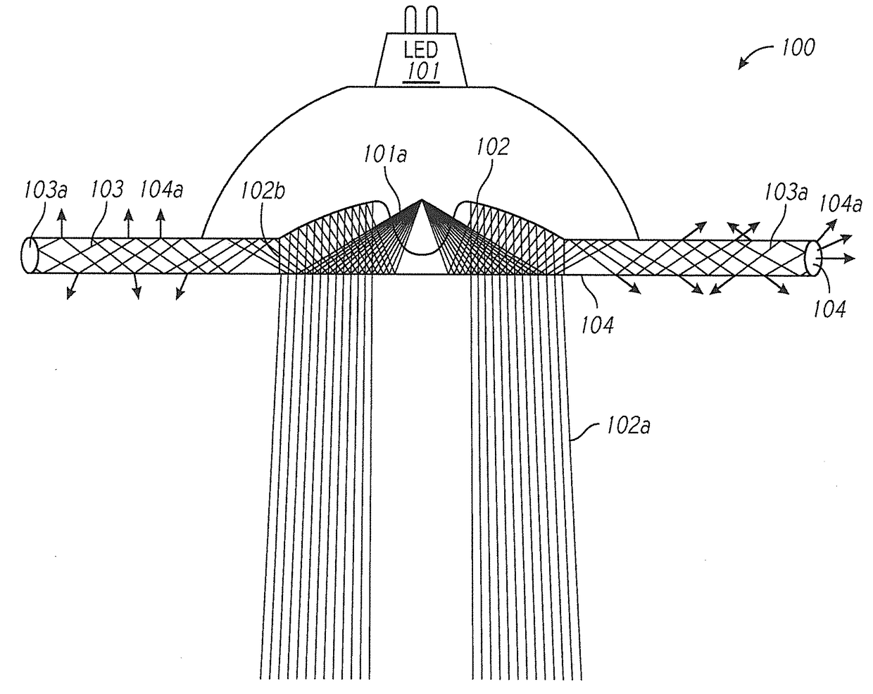
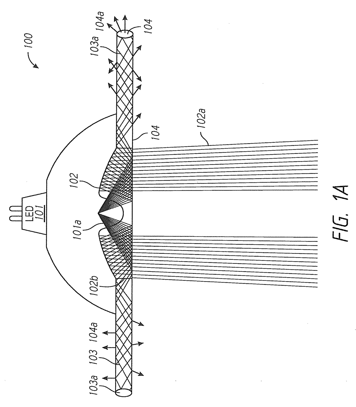
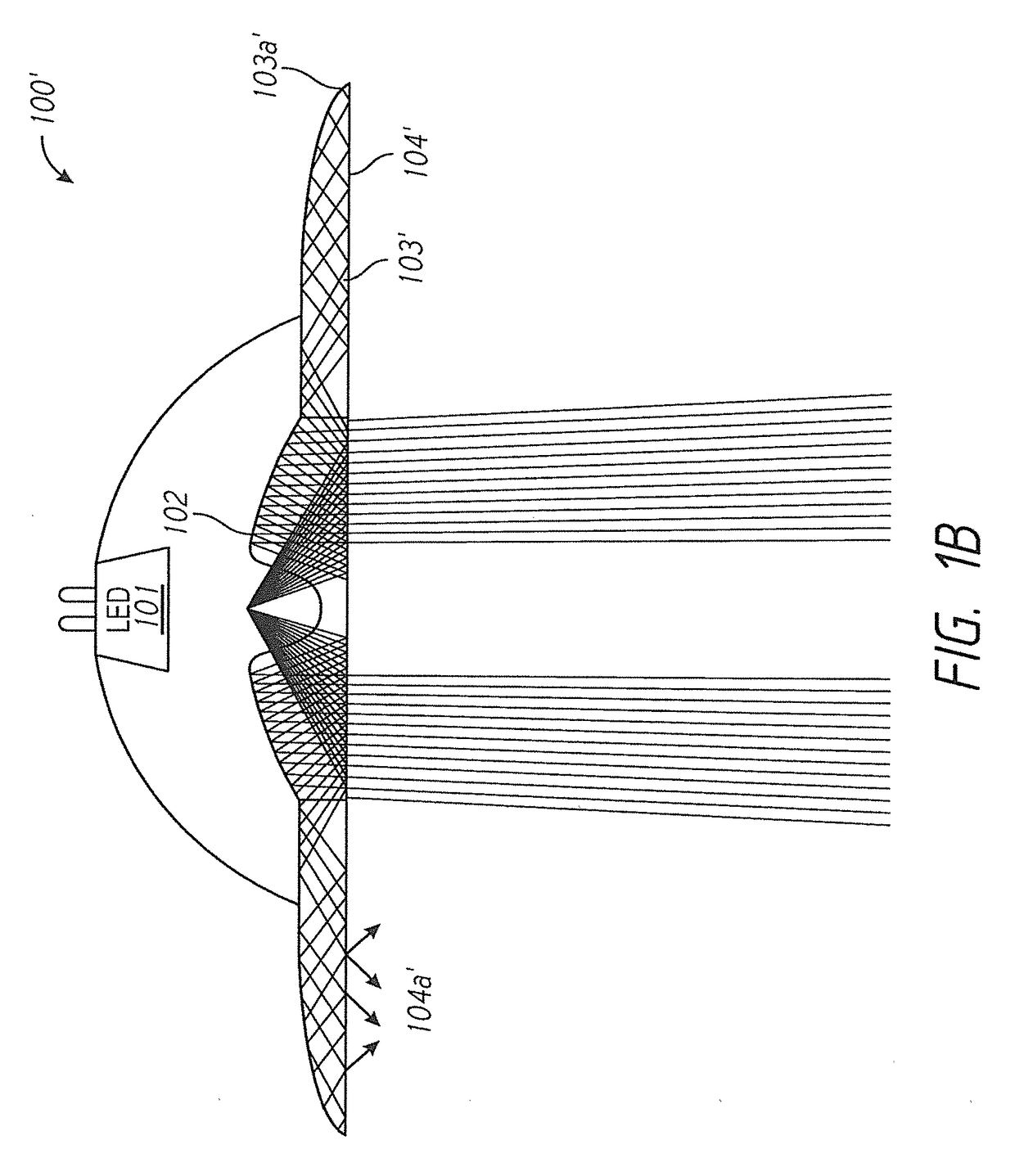
[0025]Referring to FIGS. 1A to 1C show embodiments of a luminaire providing both indirect and direct light sources, where such light sources are derived from a common plane and / or common light source. Indirect light may be generally diffuse and thus the light source may usually be a surface on a partially reflective surface or a surface otherwise configured to scatter light incident thereon. Interior surfaces of a light fixture housing may be sources of indirect light as can luminaire optics, including lenses and light guides. Thus, a direct light may typically be non-diffuse and may originate directly from a light source or be reflected by a surface, or shaped by an optic, which does not scatter the light.

[0026]Referring to FIG. 1A, one embodiment of an light-emitting diode (LED) luminaire 100 of the present invention is shown. The luminaire 100 comprises (a) at least one LED light source 101 for emitting light rays 101a; (b) at least one directional (direct) light-emitting element...


PUM


Abstract

Disclosed is an LED luminaire, comprising a housing positionable at a building structure location. The housing has at least one light output boundary and configured to direct light therein toward the light output boundary. A light guide configured to be located at the light output boundary to receive light operationally contained within the housing, so as to emit non-directional light at the light output boundary. At least one first LED light engine is located within the housing, the at least one first LED light engine including at least one first LED light source to emit directional light at the light output boundary.

Description

CROSS REFERENCE TO RELATED APPLICATIONS[0001]This application is a Continuation-in-Part of copending U.S. patent application Ser. No. 14 / 936,371, filed Nov. 9, 2015, which claims priority to U.S. Provisional Application No. 62 / 077,039, filed Nov. 7, 2014. This application is also a Continuation-in-Part of copending International PCT application No. PCT / US2015 / 059770, filed Nov. 9, 2015. The disclosures set forth in the referenced applications are incorporated herein by reference in their entireties.FIELD OF DISCLOSURE[0002]This disclosure relates generally to the field of illumination products including luminaires, and, more particularly, to a luminaire for emitting directional and non-directional light.BACKGROUND[0003]Many illumination applications (e.g., luminaires) require control of the light attributes (e.g., direction or intensity) for both functional and aesthetic purposes. For example, in a workroom, high-intensity light may be directed toward one or more specific work areas...

Claims


Application Information

Patent Timeline
Patent Type & Authority Applications(United States)
IPC IPC(8): F21V7/00F21V7/22F21V5/04F21V8/00F21V13/04
CPCF21V7/0016G02B6/0001F21Y2115/10F21V5/04F21V13/04F21V7/22F21S8/00F21S8/02F21S8/06F21Y2105/00F21Y2113/00G02B6/002G02B6/0045
Inventor PARKER, JEFFERY ROBERTSHUM, FRANKSUN, YUPINPEIFER, DONYAPHE, HOWARDMILES, ANDREWCALUORI, GIUSEPPEMIER-LANGNER, ALEJANDRO
Owner AXIS LIGHTING
Why Eureka
Try Eureka