Liquid ejecting apparatus and liquid refilling container
a technology of liquid ejecting apparatus and liquid refilling container, which is applied in the direction of printing, other printing apparatus, etc., can solve the problems of cumbersome check operation and need for much time for operation, and achieve the effect of convenient refilling
- Summary
- Abstract
- Description
- Claims
- Application Information
AI Technical Summary
Benefits of technology
Problems solved by technology
Method used
Image
Examples
first embodiment
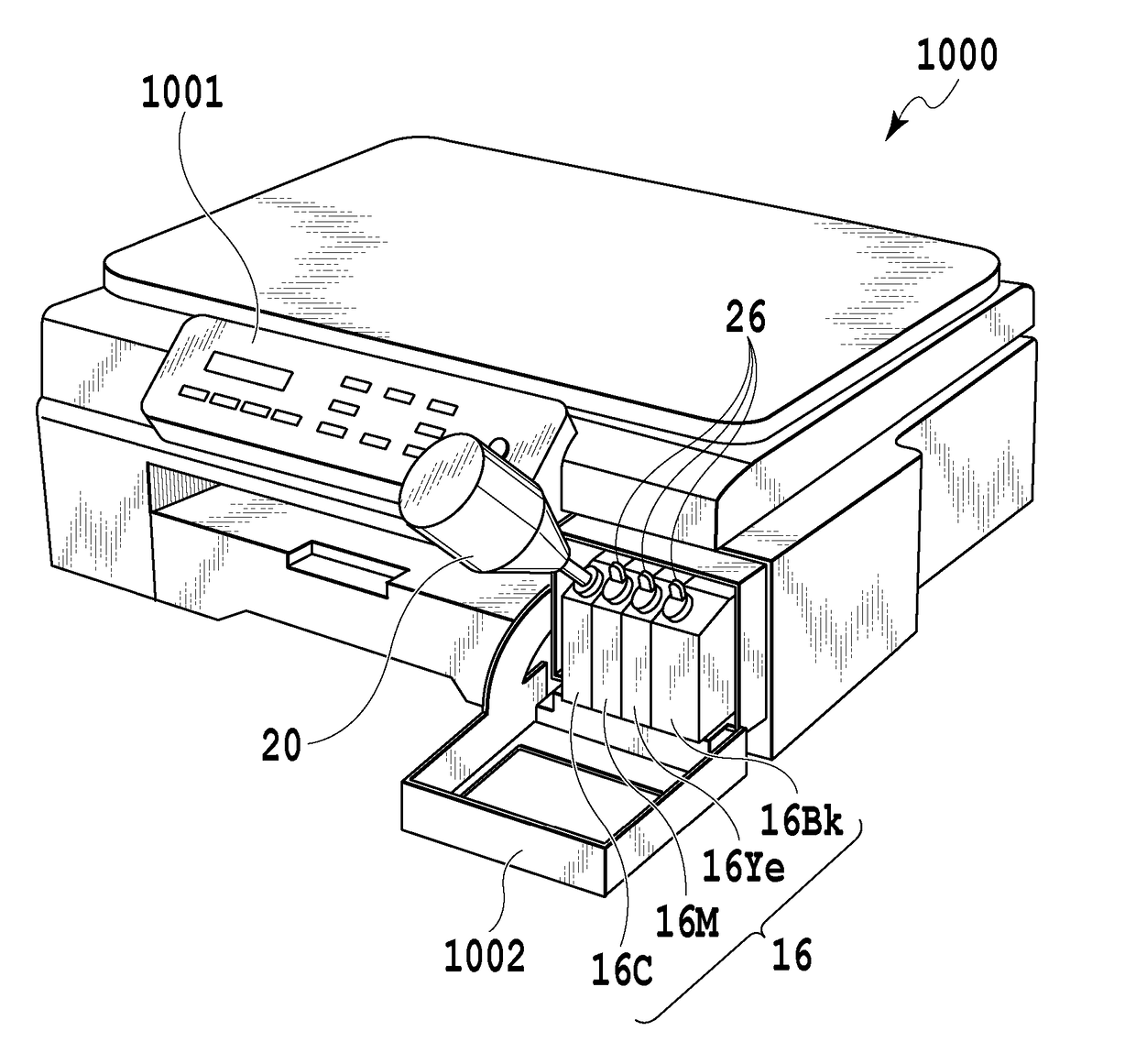
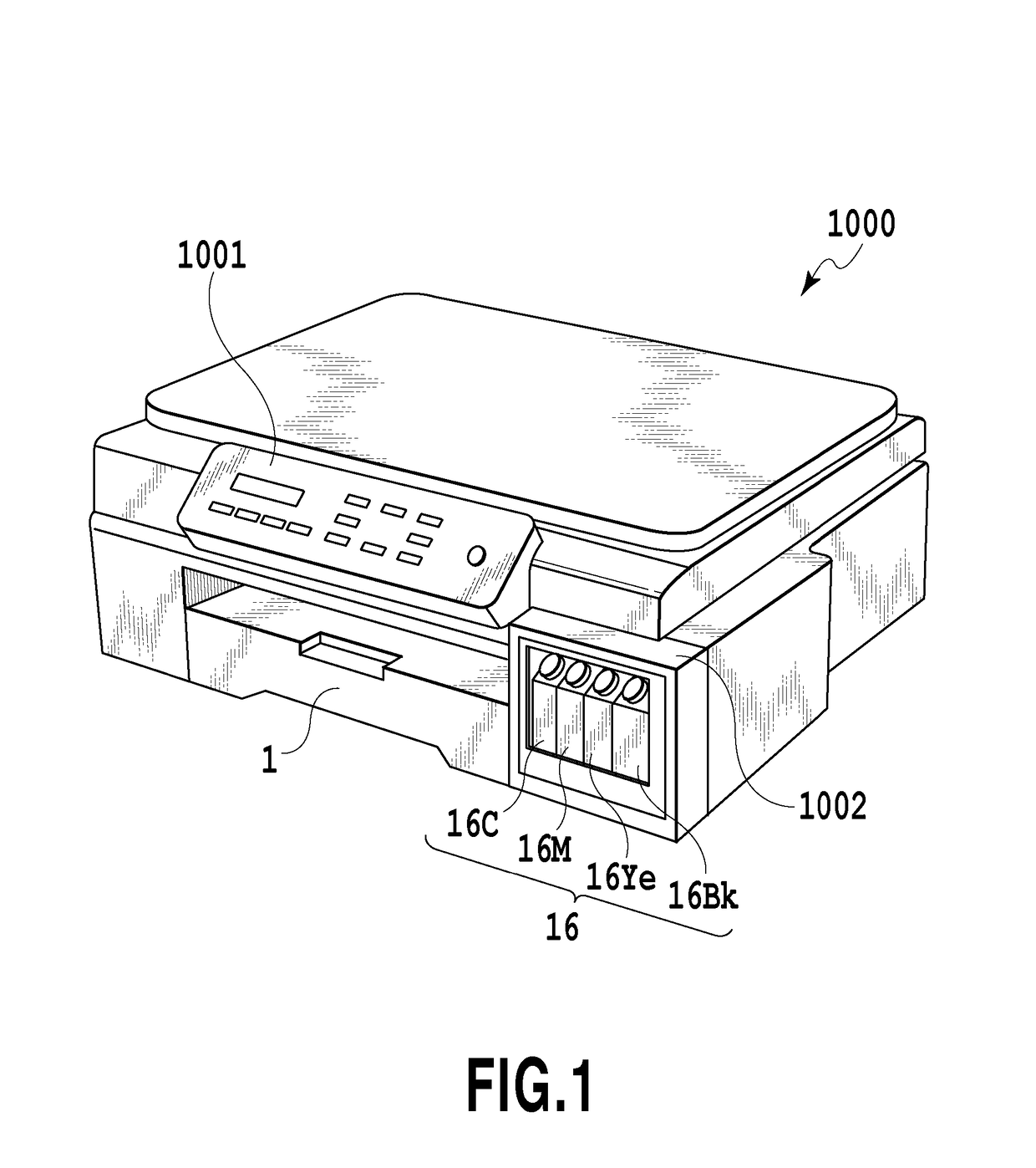
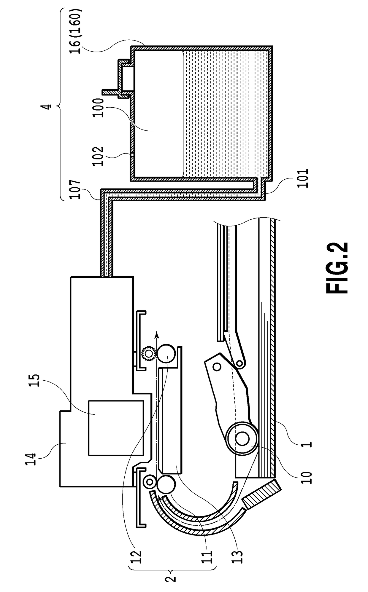
[0032]FIG. 1 is a perspective view illustrating a mechanical unit of an ink jet printing apparatus 1000 (hereinafter referred to as a printing apparatus) in an embodiment of the present invention. FIG. 2 is a longitudinal side view schematically illustrating a configuration of an essential part of the printing apparatus 1000. The mechanical unit mainly includes a first feeding unit 1, a second feeding unit 2, a printing unit 3, and a liquid supply unit 4. In the specification, “ink” is used as a general term for a liquid such as a printing liquid, a fixation treatment liquid, or a resist.
[0033]The first feeding unit 1 uses a feeding roller 10 to separate a print medium from a bundle of print media and feeds the print medium to the second feeding unit 2. The second feeding unit 2 is provided downstream of the first feeding unit 1 in a conveying direction to convey the print medium fed from the feeding roller 10, using a conveying roller 11, a discharging roller 12, and the like. A pl...
second embodiment
[0049]In the first embodiment, even in a case where the protruding portions of the ink tank 16 are not fitted into the recessed portions of the ink refilling container 20, the sealing material may be peeled off from the ink pour-out port 23 in the ink refilling container 20, and the ink tank 16 may be forcibly refilled with ink that is incompatible with the ink tank 16. Thus, a liquid ejecting apparatus in a second embodiment is configured such that ink is not injected into the ink tank 16 unless the recessed portions 24a, 24b of the ink refilling container 20 are fitted over the protruding portions 17a, 17b of the ink tank 16.
[0050]FIG. 7A and FIG. 7B are perspective views illustrating characteristic portions of the second embodiment. FIG. 8A and FIG. 8B are diagrams illustrating operations of a part of the liquid ejecting apparatus including the portions illustrated in FIG. 7A and FIG. 7B. In the figures, the same portions as those in the first embodiment or portions corresponding...
third embodiment
[0054]Now, a third embodiment of the liquid ejecting apparatus according to the present invention will be described with reference to FIGS. 9 to 15A and 15B. FIG. 9 is a perspective view illustrating the liquid ejecting apparatus in the third embodiment. FIG. 10A is a plan view illustrating a part of an ink tank serving as an ink storage container. FIG. 10B is a plan view illustrating a part of an ink refilling container serving as a liquid refilling container. FIG. 11 is a plan view illustrating a plurality of types of ink tanks. FIG. 12 is a plan view illustrating a plurality of types of ink refilling containers.
[0055]The liquid ejecting apparatus in the present embodiment includes an ink tank 160 and an ink refilling container 200 illustrated in FIG. 9. Also in the third embodiment, ink stored in a liquid storage space in the ink tank 160 is fed to the print head 15 via the ink channel 101 and the ink supply tube 107 as in the case of the first embodiment (see FIG. 2).
[0056]As il...
PUM
 Abstract
Description
Claims
Application Information
 - R&D
- Intellectual Property
- Life Sciences
- Materials
- Tech Scout
- Unparalleled Data Quality
- Higher Quality Content
- 60% Fewer Hallucinations
Browse by: Latest US Patents, China's latest patents, Technical Efficacy Thesaurus, Application Domain, Technology Topic, Popular Technical Reports.
© 2025 PatSnap. All rights reserved.Legal|Privacy policy|Modern Slavery Act Transparency Statement|Sitemap|About US| Contact US: help@patsnap.com


