Device for and Method of Connecting Two Items Together

a technology of two items and a connection method, applied in the direction of key-type connection, sheet joining, rod connection, etc., to achieve the effect of large surface area, large surface area, and bringing into engagement with the other

Active Publication Date: 2017-11-16
ROTITE
View PDF1 Cites 0 Cited by
  • Summary
  • Abstract
  • Description
  • Claims
  • Application Information

AI Technical Summary

Benefits of technology

[0008]An advantage of this invention is that each part of the device may be shallow, and a large surface area of each part may be brought into engagement with the other part of the device quickly and easily, compared with the amount of time and effort required to achieve a similar degree of engagement with a known connector / fastener, for example a screw.
[0009]The engagement forces are distributed over relatively large surface areas relatively quickly. Thus, such a device is considered to have a “mechanical advantage” compared with known connectors / fasteners.
[0010]The device provides efficient load distribution and a secure connection, in view of the frictional engagement of a large proportion of the surface area of one part of the device with the other part of the connector.

Problems solved by technology

A disadvantage of known threaded connections is that it is necessary for multiple relative revolutions of the two parts to be carried out in order to achieve a satisfactory connection which inhibits or prevents linear movement in the direction of the central, longitudinal axis.

Method used


Image

  • Device for and Method of Connecting Two Items Together
  • Device for and Method of Connecting Two Items Together
  • Device for and Method of Connecting Two Items Together

Examples


first embodiment

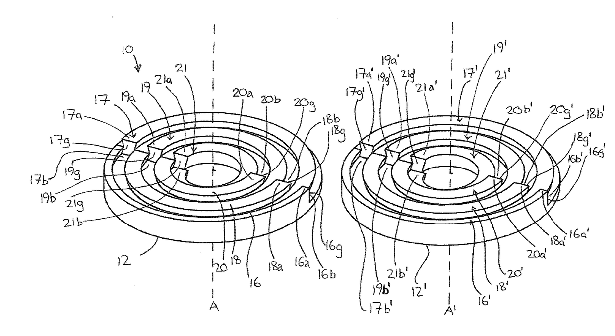
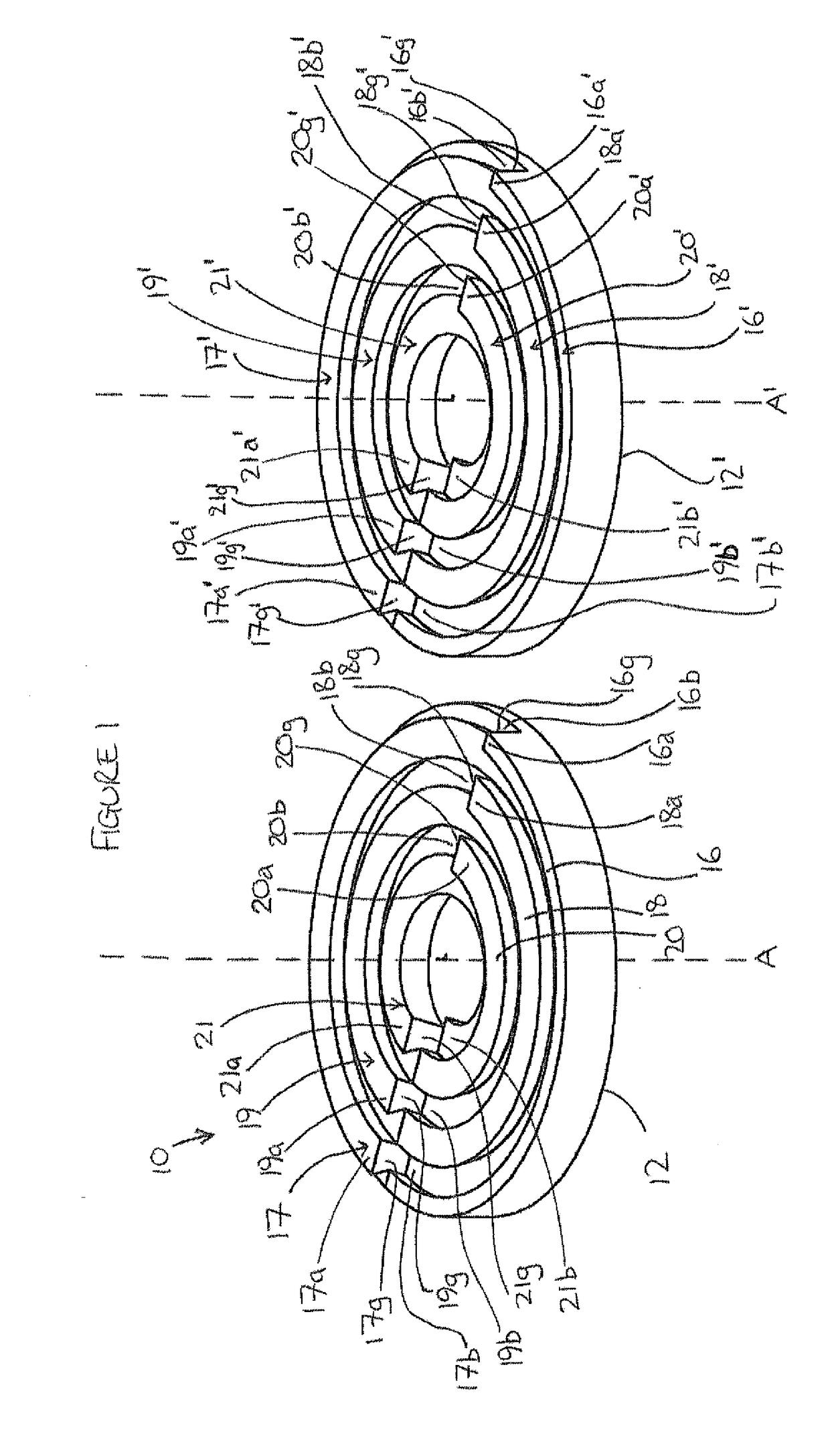
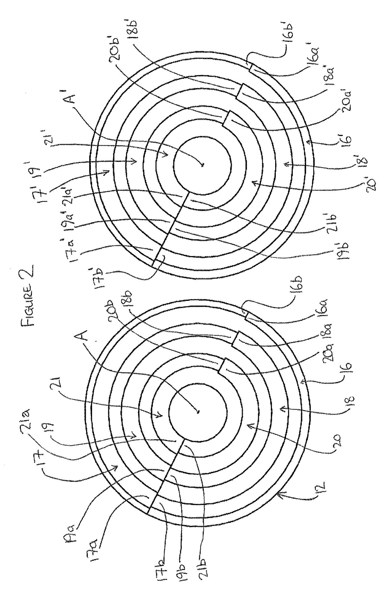
[0063]Referring to FIG. 1, there is shown the invention. A connector 10 includes a first part 12 and a second part 12′. In this embodiment of the invention, the first part and the second part are identical to one another. The first part 12 and the second part 12′ each includes a plurality of engagement formations, 16, 17, 18, 19, 20 and 21, and the second part 12′ includes a plurality of engagement formations 16′, 17′, 18′, 19′, 20′ and 21′, Whilst in the example described herein, each part 12, 12′ includes six engagement formations 16-2116′-21′, any number of engagement formations, including one, may be provided. Each of the engagement formations 16-21 and 16-21′ is substantially annular and has a first end 16a, 17a, 18a, 19a, 20a, 21a, 16a′, 17a′, 18a′, 19a′, 20a′, 21a″, and a second end 16b, 17b, 18b, 19b, 20b, 21b, 22b, 16b′, 17b′, 18b′, 19b′, 20b′ and 21b′. Each engagement formation 16-21, 16′-21′ has a first portion which extends between the first end 16a-21a, 16a′-21a′ of the...

second embodiment

[0081]the invention 110 is shown in FIGS. 5 to 7. The connector 110 is similar to the connector 10, and similar features are referenced with similar reference numerals, prefixed with “1”. The connector 110 is an example of a “quadruple pick-up”, 90° rotation connector.

[0082]The connector 110 includes two parts 112 and 112′. The two parts 112 and 112′ are not identical, but are engageable with one another. Each part 112, 112′ has a respective connecting face which is substantially transverse to a longitudinal axis B, B′ of the respective part 112, 112′.

[0083]The first part includes a plurality of engagement formations 116, 117, 118, 119. The engagement formations 116-119 are substantially annular, and are concentric about a longitudinal axis B. Each engagement formation 116-119 extends axially, in a direction which is substantially parallel to the longitudinal axis B. Each engagement formation 116-119 is separated from an adjacent engagement formation by a receiving formation 120, 12...

third embodiment

[0097]the invention is shown in FIGS. 8 to 10. A connector 210 includes two parts 212, 212′. The first part 212 includes a plurality of engagement formations 216, 217, 218, 219, 220. The engagement formations 216-220 are substantially annular and concentric about a longitudinal axis C. Each engagement formation 216-220 includes two sectors X, Y. However, each part 212, 212′ may have any number of sectors. Each sector X, Y has a first end, a second end, an upper surface, and a lower surface. Each sector X, Y of each engagement formation 216-220 also includes an inner circumferential wall and an outer circumferential wall which, together, form two substantially circular side walls. The upper surface of each sector X, Y of each engagement formation 216-220 is substantially helicoidal. Each sector X, Y of each engagement formation 216-220 includes an end face which is positioned at the first end of the sector X, Y, and which is generally transverse to the side walls and the upper surfac...


PUM

PropertyMeasurementUnit
angleaaaaaaaaaa
angleaaaaaaaaaa
angleaaaaaaaaaa

Abstract

A device includes first and second inter-engageable parts, each having a longitudinal axis and a connecting face extending substantially transversely to the longitudinal axis. The first part has an engagement formation extending substantially axially and the second part has a receiving formation extending substantially axially, and in which the engagement formation is receivable. The engagement and receiving formations each includes a substantially helicoidal surface extending at least partially around the longitudinal axis of the respective part of the connector, so that rotation of the parts relative to one another about the longitudinal axes, when the parts are substantially co-axially aligned, so that the connecting faces of the parts face one another in a substantially axial direction, causes engagement of the engagement formation with the corresponding receiving formation.

Description

CROSS-REFERENCE TO RELATED APPLICATIONS[0001]This application is a continuation of U.S. patent application Ser. No. 13 / 818,673, filed Aug. 26, 2016, which is a National Phase of International Application No. PCT / GB2011 / 051617, filed Feb. 25, 2013, which claims priority to UK Application No. GB 1014263.6, filed Aug. 26, 2010, the disclosures of which are incorporated herein by reference in their entirety.BACKGROUND OF THE INVENTION[0002]This invention relates to a device which may be used, and hereinafter is described principally in relation to its use, as a connector. However, it will be understood that the device may be used for other purposes, a number of which will be referred to below.[0003]It is known to connect items together by means of connectors or fasteners. Fasteners and connectors including threaded portions are known, for example screws, and screw caps.[0004]A screw includes a body and a generally helicoidal projection which extends radially outwardly of the body, along...

Claims


Application Information

Patent Timeline
Patent Type & Authority Applications(United States)
IPC IPC(8): F16B7/18F16B33/02F16B21/02F16B3/00F16B7/20
CPCF16B7/18F16B33/02F16B21/02Y10T29/49881F16B7/182F16B3/00Y10T403/68F16B7/20F16B5/008H01R13/62H01R24/84F16B7/00
Inventor BURNS, STUART
Owner ROTITE
Why Eureka
Try Eureka