Walking cane clamp and base for use with walkers and rollators

Active Publication Date: 2017-11-23
MEDICAL DEPOT
View PDF1 Cites 13 Cited by
  • Summary
  • Abstract
  • Description
  • Claims
  • Application Information

AI Technical Summary

Benefits of technology

[0006]A walker or rollator is provided which includes a pair of side frames, each side frame including a front leg, a rear leg, at least one hand rail, and at least one cross-member joining each side frame, and a walking cane clamp which includes a clip dimensioned and configured to secure the walking cane clamp to the walker or rollator, the clip being attached to a cane fastener, the cane fastener including a body portion and a biasing member pivotally attached to the body portion, the body portion defining an opening and a receptacle dimensioned and configured to receive a portion of a cane shaft, the biasing member defining an open position and a closed position of the receptacle, the biasing member being pivotally biased toward the closed position in which a portion of the biasing member covers a portion of the opening sufficient to secure the cane shaft within the receptacle. In embodiments, the walker or rollator includes a base for receiving the walking cane, the base for receiving the walking cane including a base clip for securing the walking cane base to the walker or rollator, the base for receiving the walking cane including a receptacle for receiving an end of the walking cane, wherein the walking cane clamp and the base for receiving the walking cane cooperate to secure the walking cane to the walker or rollator. In embodiments, the walking cane clamp and the base for receiving the walking cane are both secured to a sing

Problems solved by technology

Walkers and rollators are relatively large and typically require the user to operate them with one or both hands during ambulation.
As a result, the user may find it difficult or clumsy to carry objects while using them.
Since walkers and rollators are relativel

Method used


Image

  • Walking cane clamp and base for use with walkers and rollators
  • Walking cane clamp and base for use with walkers and rollators
  • Walking cane clamp and base for use with walkers and rollators

Examples


Embodiment Construction

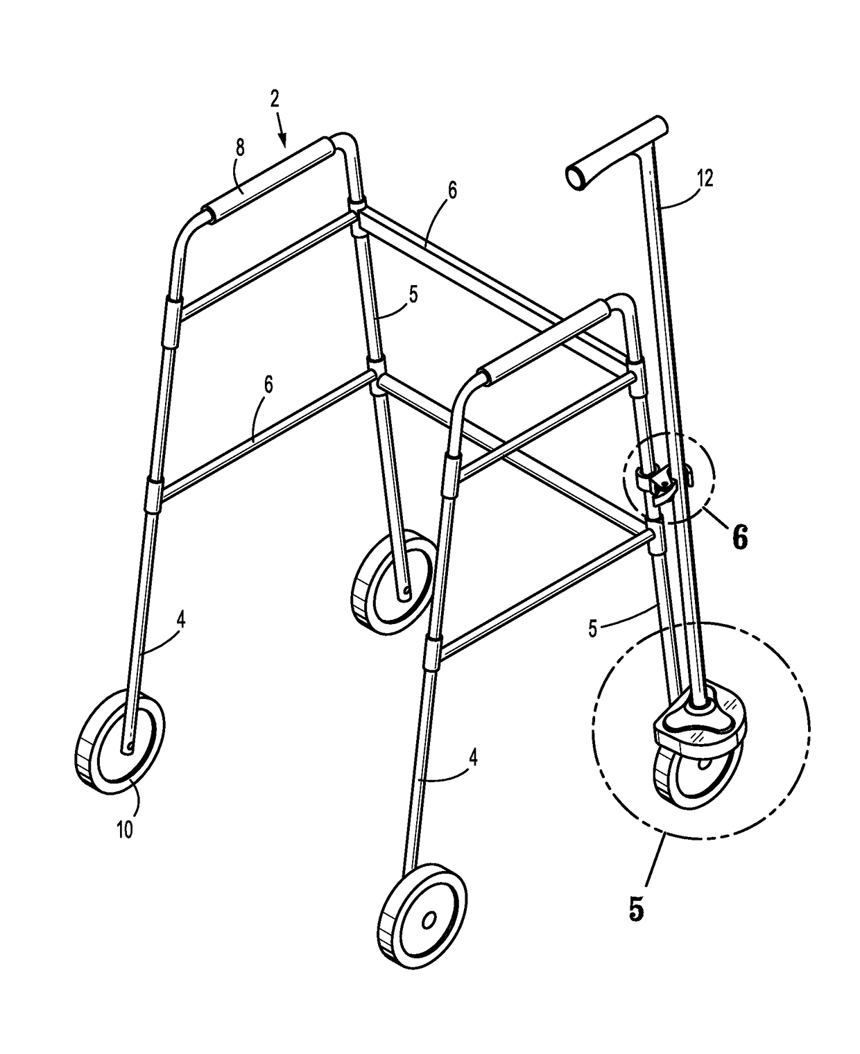
[0025]Provided herein is a walking cane clamp (the “clamp”) for securing the walking cane to a walker or a rollator. In embodiments, the clamp cooperates with a base for receiving an end of the walking cane. The walking cane clamp allows the user of a walker or rollator to use the walker or rollator as a way to transport a walking cane to various locations, thereby allowing the user to easily switch back and forth between using the walker or rollator and the walking cane at those locations. The clamp is spring loaded and provides a convenient modality for a user to secure a walking cane to the clamp by simply pushing the cane into place. The clamp is amenable to one-handed operation for release of the cane from the clamp when desired.

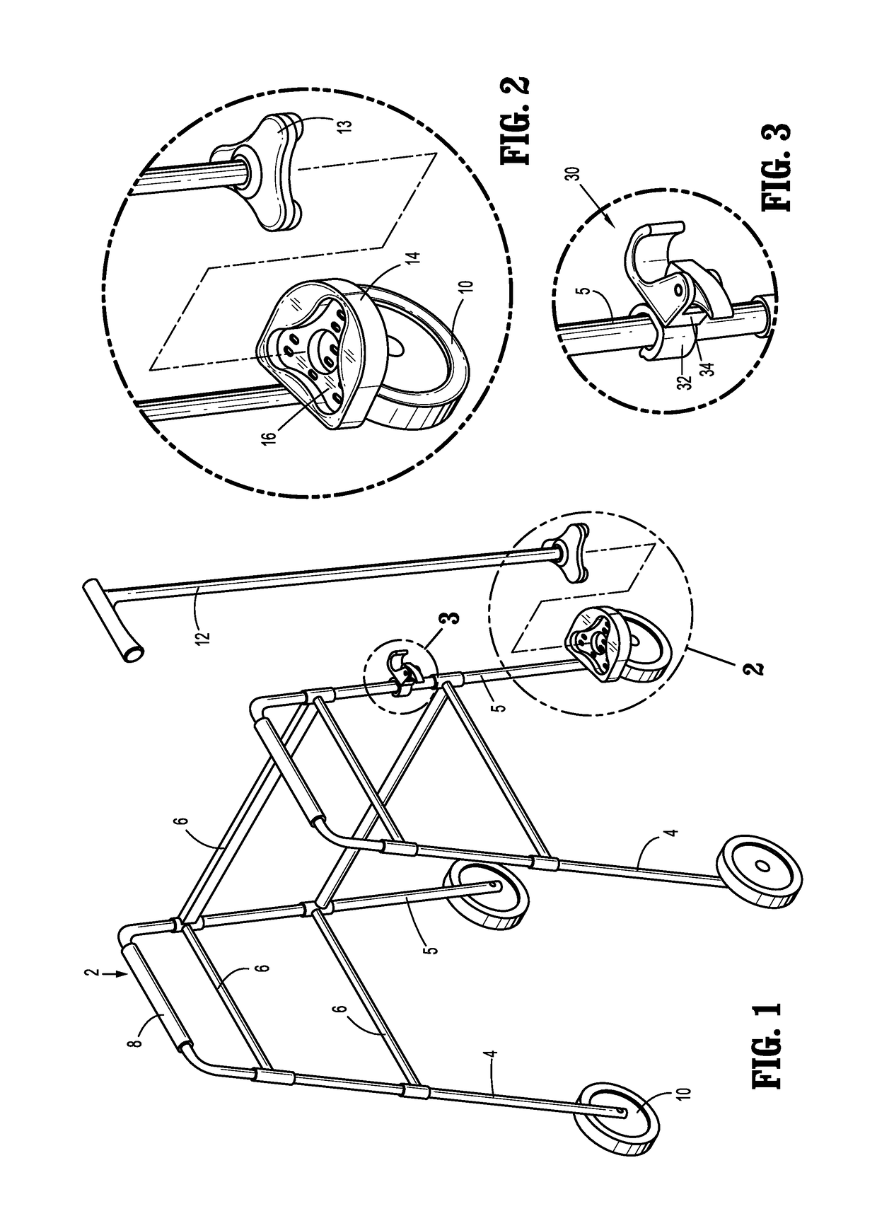
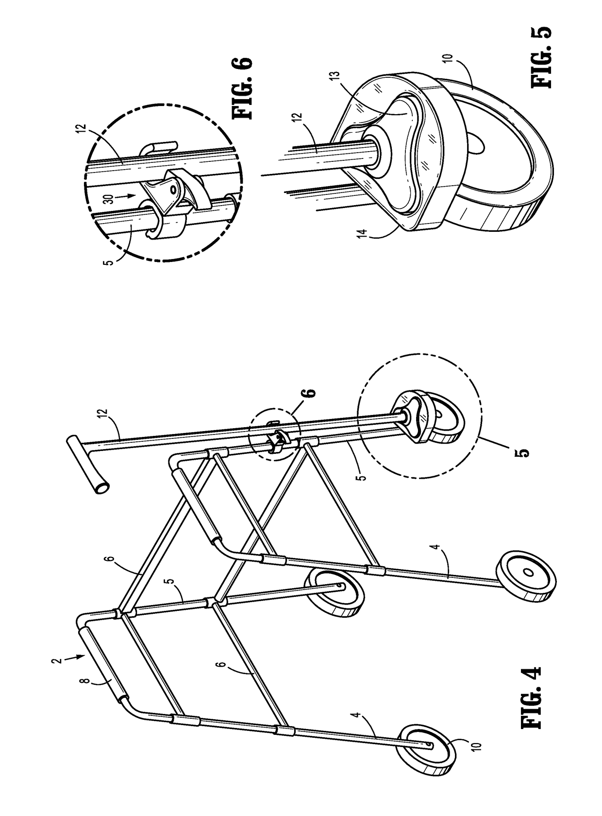
[0026]As depicted in the drawings, a conventional rollator 2 or walker 2′ includes vertically and horizontally disposed tubing assembled into a pair of side frames, each side frame including a rear leg 4, a front leg 5, and a hand rail or grip 8. The tw...


PUM


Abstract

A walking cane clamp is provided which includes a clip dimensioned and configured to releasably secure the walking cane clamp to a support member, the clip being attached to a cane fastener, the cane fastener including a body portion and a biasing member pivotally attached to the body portion, the body portion defining an opening and a receptacle dimensioned and configured to receive a portion of a cane shaft, the biasing member defining an open position and a closed position of the receptacle, the biasing member being pivotally biased toward the closed position in which a portion of the biasing member covers a portion of the opening sufficient to secure the cane shaft within the receptacle. Also provided is a system for securing a walking cane to a walker or a rollator which includes a walking cane clamp as described herein and a base for receiving the walking cane. Also provided is a walker or rollator which includes a walking cane clamp as described herein and an optional base for receiving a walking cane.

Description

CROSS-REFERENCE TO RELATED APPLICATIONS[0001]This application claims the benefit of, and priority to, U.S. Design Pat. Application No. 29 / 565,598, filed on May 23, 2016, and U.S. Design Pat. Application No. 29 / 565,600, filed on May 23, 2016, both of which are hereby incorporated herein by reference in their respective entireties.BACKGROUND1. Technical Field[0002]This disclosure relates to devices for securing walking canes to walkers and rollators.2. Description of Related Art[0003]Walking canes, walkers and rollators are well-known aids for assisting mobility of elderly, infirm or injured patients. Walkers and rollators typically provide the user with a great deal of stability and support, especially, e.g., when the user is frail or experiencing problems with balance. Walkers and rollators are relatively large and typically require the user to operate them with one or both hands during ambulation. As a result, the user may find it difficult or clumsy to carry objects while using th...

Claims


Application Information

Patent Timeline
IPC IPC(8): A45B1/04A45B9/04A61H3/04A61H3/00
CPCA45B1/04A61H2003/002A45B9/04A61H3/04A45B3/00A61H2003/025A61H2003/0261
Inventor KAPLAN, GARRETH
Owner MEDICAL DEPOT
Why Eureka
Try Eureka