
Split chord deployable wing

a technology of deployable wings and chords, applied in aircrafts, transportation and packaging, weapons, etc., can solve the problems of limited chord length of wings and lack of rigidity of unitary wings required of many aerial vehicles and missions

Inactive Publication Date: 2017-11-23
RAYTHEON CO
View PDF2 Cites 5 Cited by
  • Summary
  • Abstract
  • Description
  • Claims
  • Application Information

AI Technical Summary

Benefits of technology

This patent describes a design for a wing section that is made up of two halves that fit together like a lock and key. The surface of the wing has complementary parts that fit together to form a single interlocking section. This design ensures stability and strength, both vertical and shear, which can withstand heavy loads.

Problems solved by technology

The wing's chord length is limited by the space constraints and ability to stow the wings.
However, these wings lack the rigidity of a unitary wing required of many aerial vehicles and missions.

Method used


Image

  • Split chord deployable wing
  • Split chord deployable wing
  • Split chord deployable wing

Examples


Embodiment Construction

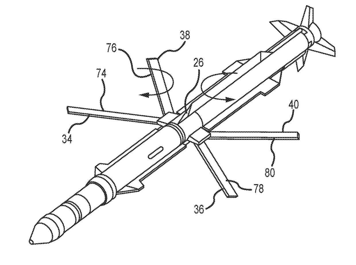
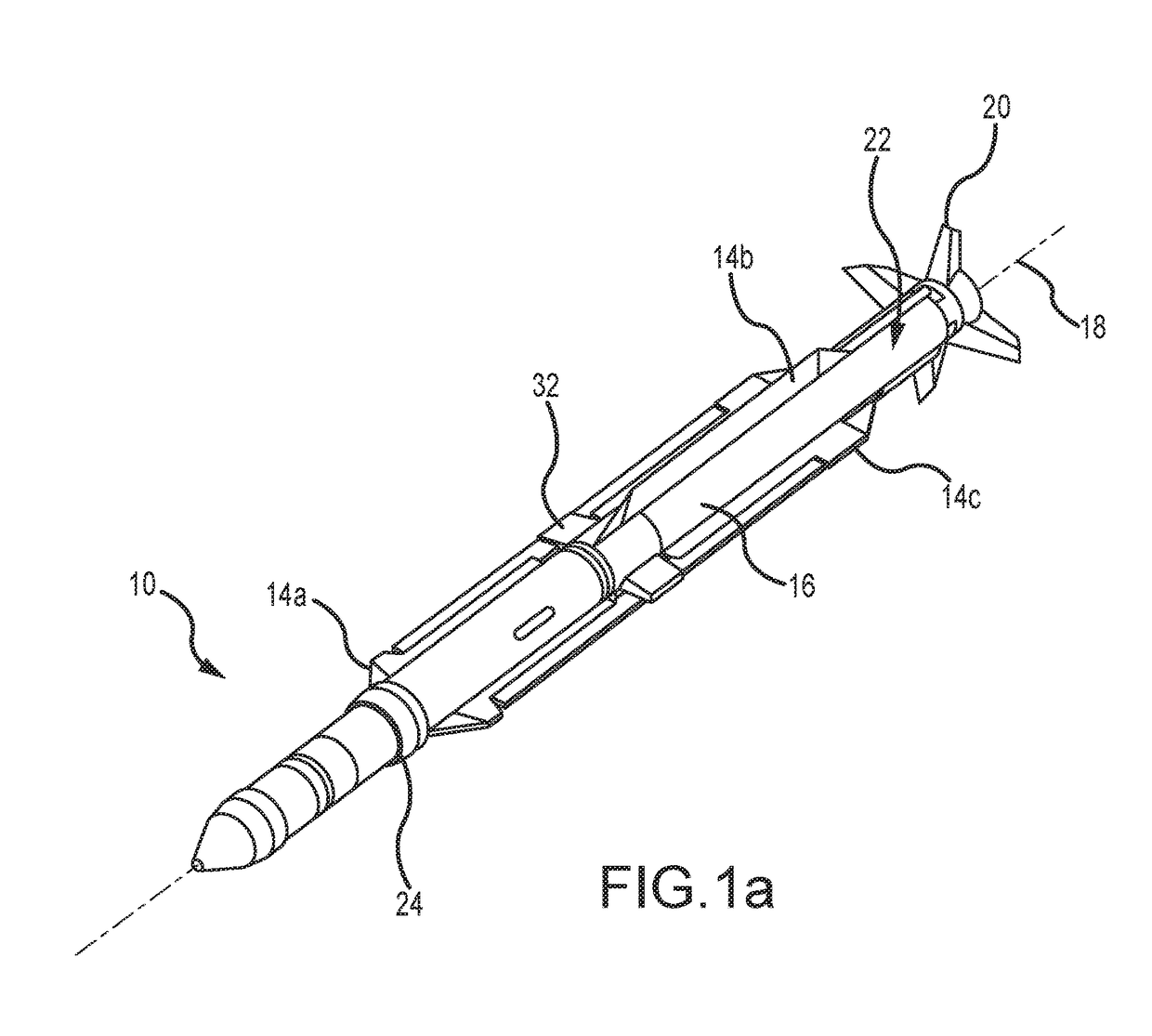
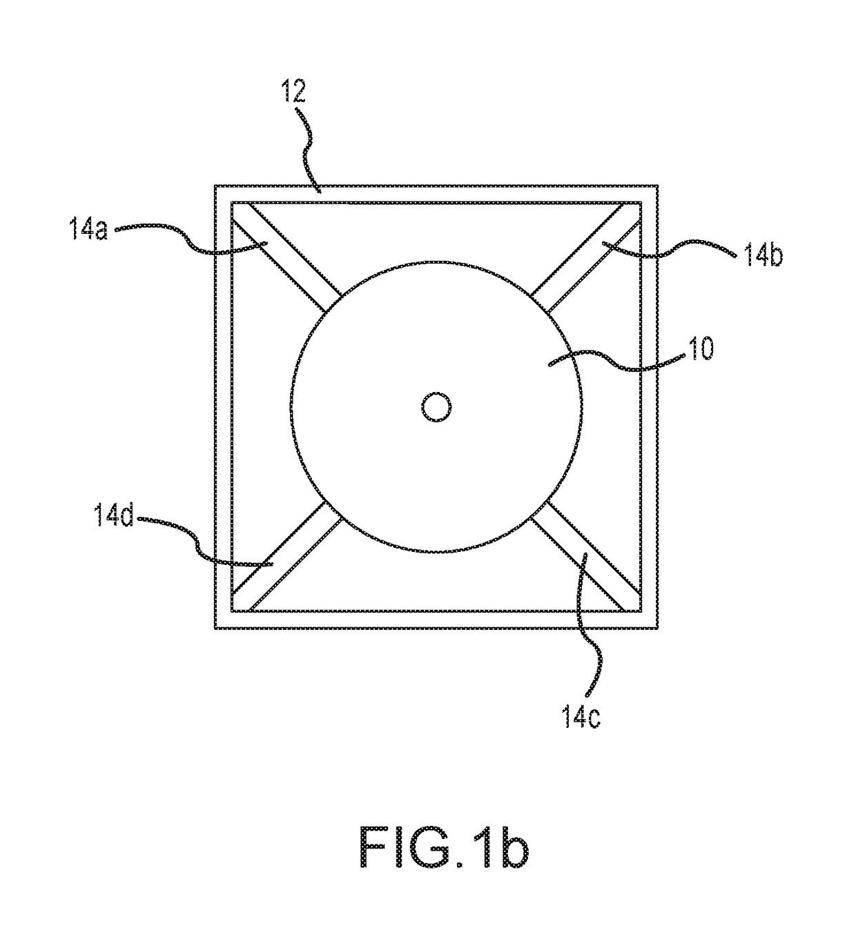
[0022]The present invention describes a split-chord deployable wing for aerial vehicles such as missiles, UAVs, MALDs and SDBs that require both longer wing span and increased chord length. Such split-chord deployable wings must address unique problems such as synchronized deployment and integrity of the deployed wing to both vertical and sheer loads. Each wing comprises a pair of wing sections stowed fore and aft along the fuselage. Complementary gear teeth synchronize deployment of the wing sections. A deployment mechanism synchronizes deployment of the wings. Complementary tongue and groove surface portions of the wing sections progressive engage as the wing sections pivot away from the fuselage. The surface portions are segmented so that tongue segments are nested within complementary groove segments to provide both vertical and sheer stability.

[0023]Referring now to FIGS. 1a-1d and 2a-2b, an embodiment of a tube-launched missile includes a missile 10 initially stowed inside a l...


PUM


Abstract

A split-chord deployable wing for aerial vehicles such as missiles, UAVs, MALDs and SDBs that require both longer wing span and increased chord length. Such split-chord deployable wings must address unique problems such as synchronized deployment and integrity of the deployed wing to both vertical and sheer loads. Each wing comprises a pair of wing sections stowed fore and aft along the fuselage. Complementary gear teeth synchronize deployment of the wing sections. A deployment mechanism synchronizes deployment of the wings. Complementary tongue and groove surface portions of the wing sections progressive engage as the wing sections pivot away from the fuselage. The surface portions are segmented so that tongue segments are nested within complementary groove segments to provide both vertical and sheer stability.

Description

BACKGROUND OF THE INVENTIONField of the Invention[0001]This invention relates to deployable wings for missiles, unmanned aerial vehicles (UAVs), miniature air launched decoys (MALDs), small diameter bombs (SDBs) and the like.Description of the Related Art[0002]Container or tube launched aerial vehicles such as missiles, UAVs, MALDS, SDBs require the wings to be in a stowed position along or inside the fuselage and to transition to a deployed position upon launch. The pair of wings may be stowed along the center-line of the vehicle either against or recessed within the fuselage or may be stowed on top of the vehicle. A deployment mechanisms such as springs, gas springs, and motors to deploy the wings. In most cases these systems are configured to deploy the wings in sync. The wing's chord length is limited by the space constraints and ability to stow the wings. There are many instances of deployable wings to provide wingspan and chord length. However, these wings lack the rigidity of...

Claims


Application Information

Patent Timeline
Patent Type & Authority Applications(United States)
IPC IPC(8): F42B10/14F42B15/01B64C3/56B64C39/02
CPCF42B10/14B64C39/024B64C3/56B64C2201/102B64C2201/08B64C2201/021F42B15/01B64U30/12B64U10/25B64U70/50
Inventor MEREMS, PAUL A.
Owner RAYTHEON CO
Learn More