
Clamps for installation of photovoltaic modules to roofs

Inactive Publication Date: 2017-11-23
FTC SOLAR INC
View PDF0 Cites 8 Cited by
  • Summary
  • Abstract
  • Description
  • Claims
  • Application Information

AI Technical Summary

Benefits of technology

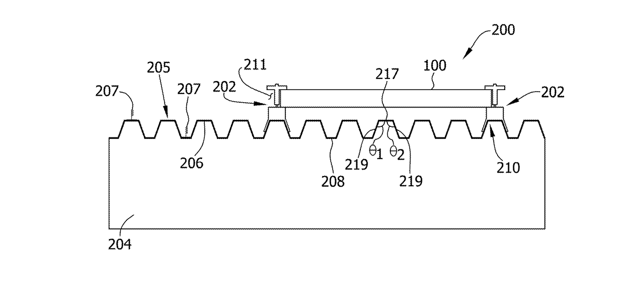
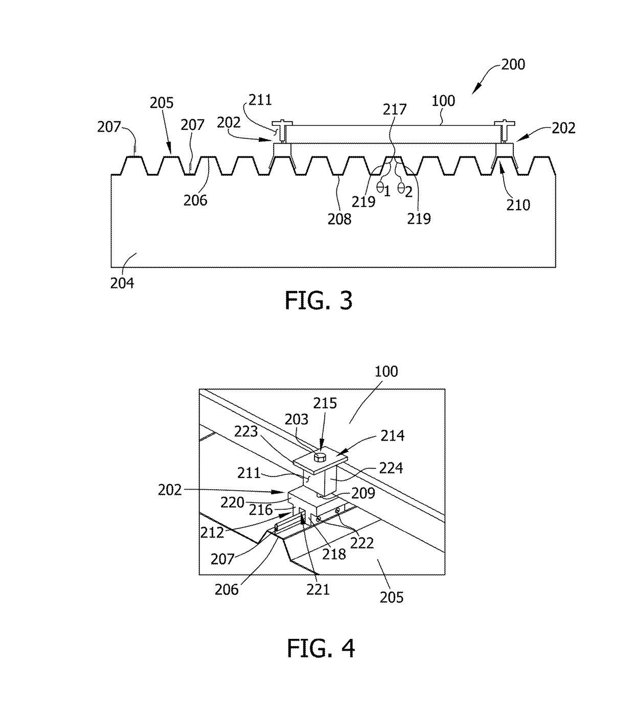
The patent describes a solar module clamp that can securely attach a solar module to a structure. The clamp includes a base, a t-shaped bracket, and a fastener. The base is attached to the structure and has three segments connected together. The bracket has two parts that are connected to the base. The fastener extends through both parts of the bracket and is connected to the base. This clamp can selectively apply a force to the solar module, allowing it to be securely fastened to the structure. The patent also describes various refinements and combinations of features that can be incorporated into the clamp. Overall, this invention provides a simple yet effective tool for securing solar modules to buildings.

Problems solved by technology

Water and weight by ballast may diminish and / or damage the structural integrity of the roof and the building.
Mounting surfaces on a structure which support solar module racks are not typically simple, flat surfaces.

Method used


Image

  • Clamps for installation of photovoltaic modules to roofs
  • Clamps for installation of photovoltaic modules to roofs
  • Clamps for installation of photovoltaic modules to roofs

Examples


Embodiment Construction

[0031]This disclosure relates generally to mounting systems for solar modules and, more specifically, to clamps for mounting solar modules to a mounting surface of a structure.

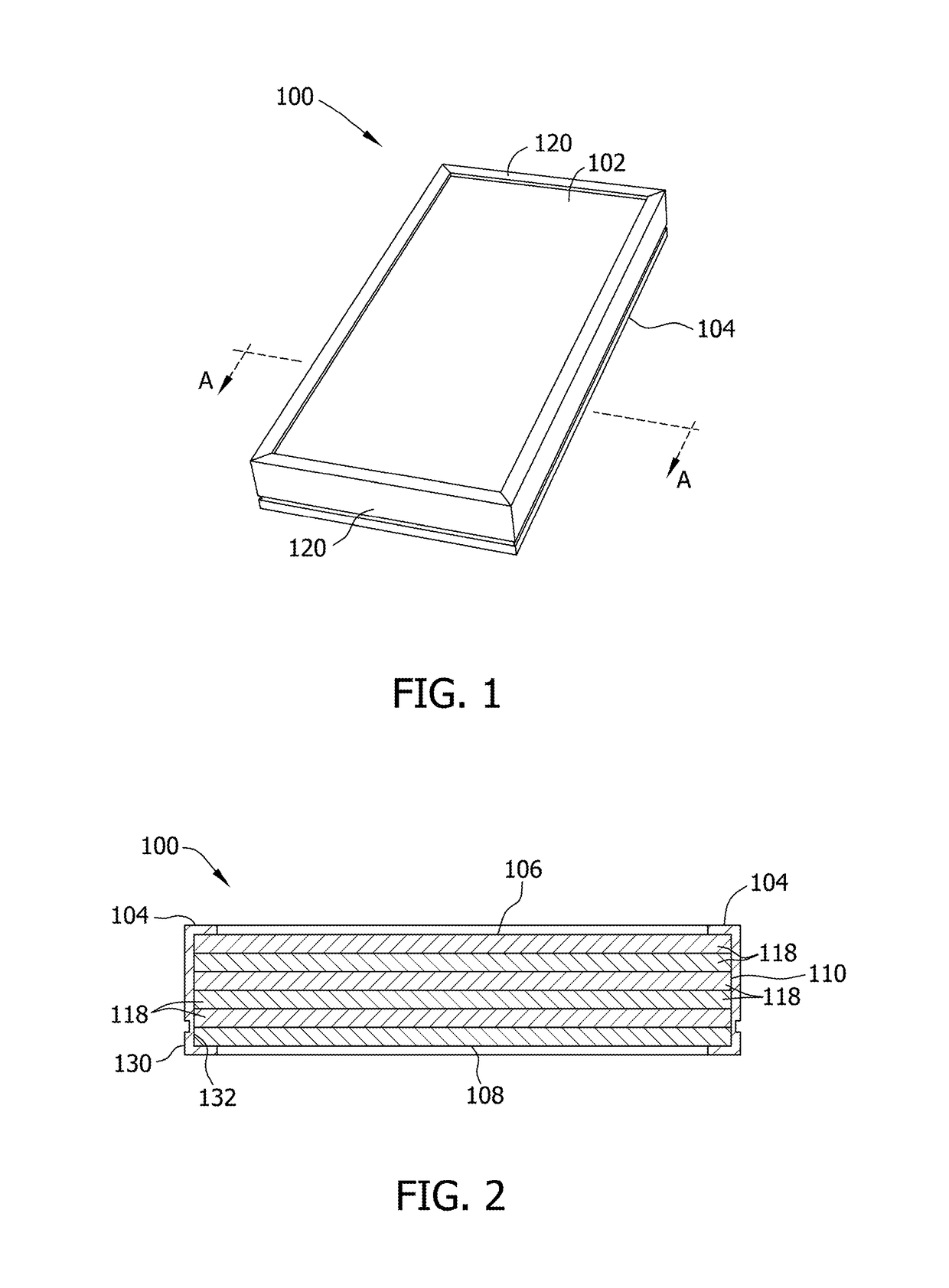
[0032]Referring initially to FIGS. 1 and 2, a solar module of one embodiment is indicated generally at 100. A perspective view of solar module 100 is shown in FIG. 1. FIG. 2 is a cross-sectional view of solar module 100 taken at line A-A as shown in FIG. 1. Solar module 100 includes a solar laminate 102 and a frame 104 circumscribing solar laminate 102.

[0033]Solar laminate 102 includes a top surface 106 and a bottom surface 108 (shown in FIG. 2). Edges 110 extend between top surface 106 and bottom surface 108. In this embodiment, solar laminate 102 is rectangular shaped. In other embodiments, solar laminate 102 may have any suitable shape.

[0034]As shown in FIG. 2, the solar laminate 102 has a laminate structure that includes several layers 118. Layers 118 may include, for example, glass layers, non-reflective ...


PUM


Abstract

Clamping assemblies for securing a solar module to a structure include a base, a bracket, and a fastener. The base may be attached to a multi-planar roof of the structure. The base and the bracket together define a mounting region for receiving a portion of the solar module. The fastener connects the base and the clamp and can selectively apply a clamping force to the portion of the solar module.

Description

CROSS-REFERENCE TO RELATED APPLICATION[0001]This application claims priority to U.S. Provisional Patent Application No. 62 / 069,083 filed on 27 Oct. 2014, the entire disclosure of which is hereby incorporated by reference in its entirety.FIELD[0002]This disclosure relates generally to mounting systems for solar modules and, more specifically, to clamps for mounting solar modules to a mounting surface of a structure.BACKGROUND[0003]Solar modules are devices which convert solar energy into other forms of useful energy (e.g., electricity or thermal energy). Such modules are typically positioned above an underlying support surface by a rack. This rack may be configured to position the solar module at an angle relative to the support surface to minimize an angle of incidence between the solar module and the sun's rays. Minimizing this angle of incidence increases the amount of solar energy gathered by the solar module.[0004]When the underlying surface is the roof of a structure, the racks...

Claims


Application Information

Patent Timeline
IPC IPC(8): H02S20/23F16B2/12F24J2/52H02S30/10F24J2/46
CPCH02S20/23F24J2/5249F24J2002/4663H02S30/10F16B2/12F24J2/5258F24S25/615F24S25/636F24S2025/6003Y02B10/10Y02B10/20Y02E10/47Y02E10/50
Inventor PRAKASH, MARATHMAPATI, ANURAGMALAPAREDDY, BHARATRAMASAMY, SELVAMNARAYANAN, MANICKAMMANAPAT, RAJESHCHERUKUPALLI, NAGENDRA SRINIVAS
Owner FTC SOLAR INC
Learn More