Adjustable connector for refrigerant pipe

Active Publication Date: 2017-11-30
CHIU SHENG YUNG
View PDF1 Cites 3 Cited by
  • Summary
  • Abstract
  • Description
  • Claims
  • Application Information

AI Technical Summary

Benefits of technology

[0005]The major objective of the present disclosure is to provide an adjustable connector for solving the aforementioned problems. When being mounted on the valve spout of the refrigerant pipe, the adjustable connector may be separated from the refrigerant pipe quickly when it is found that the refrigerant is escaped, so

Problems solved by technology

The aforesaid refrigerant is highly flammable.
However, it's difficult to complete the action of rotating the button 94 to release the valve pin 95 in a short period of time.
Therefore, the time period in which the r

Method used


Image

  • Adjustable connector for refrigerant pipe
  • Adjustable connector for refrigerant pipe
  • Adjustable connector for refrigerant pipe

Examples


Embodiment Construction

[0020]The accompanying drawings are included to provide a further understanding of the present disclosure, and are incorporated in and constitute a part of this specification. The drawings illustrate exemplary embodiments of the present disclosure and, together with the description, serve to explain the principles of the present disclosure.

[0021]Please refer to FIG. 1 to FIG. 8, which respectively illustrate the embodiments of the present disclosure, and the present figures are not limited thereto of the present disclosure.

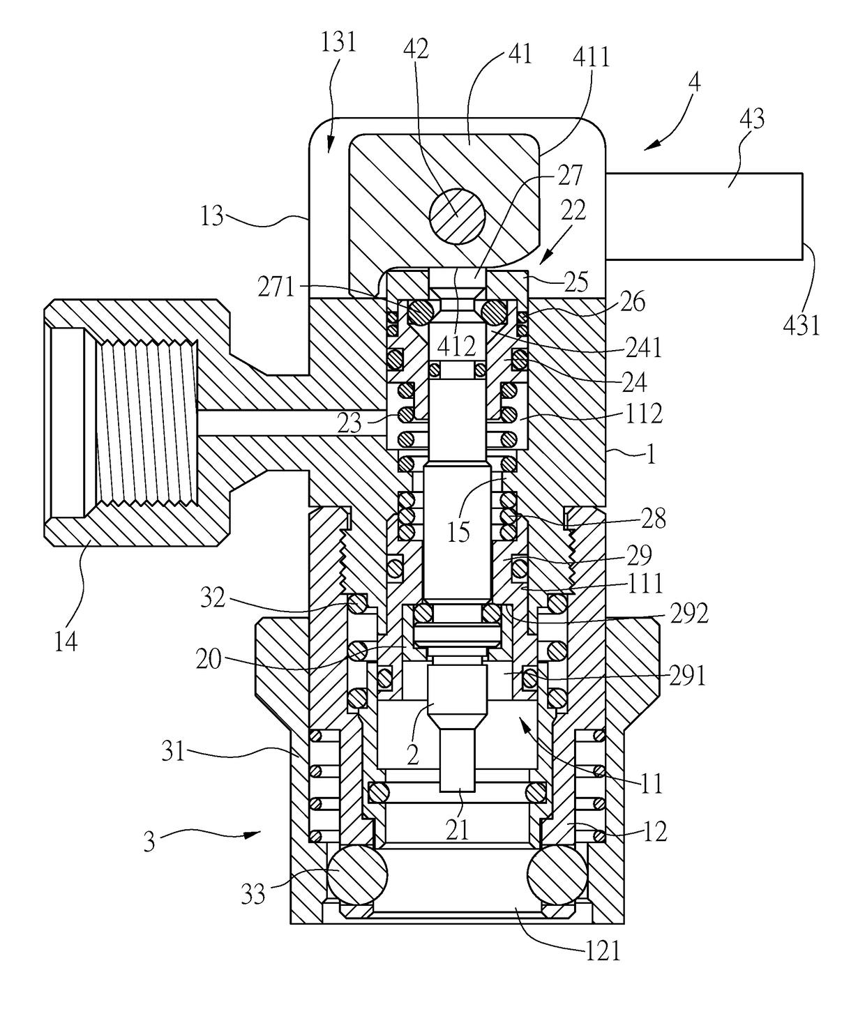
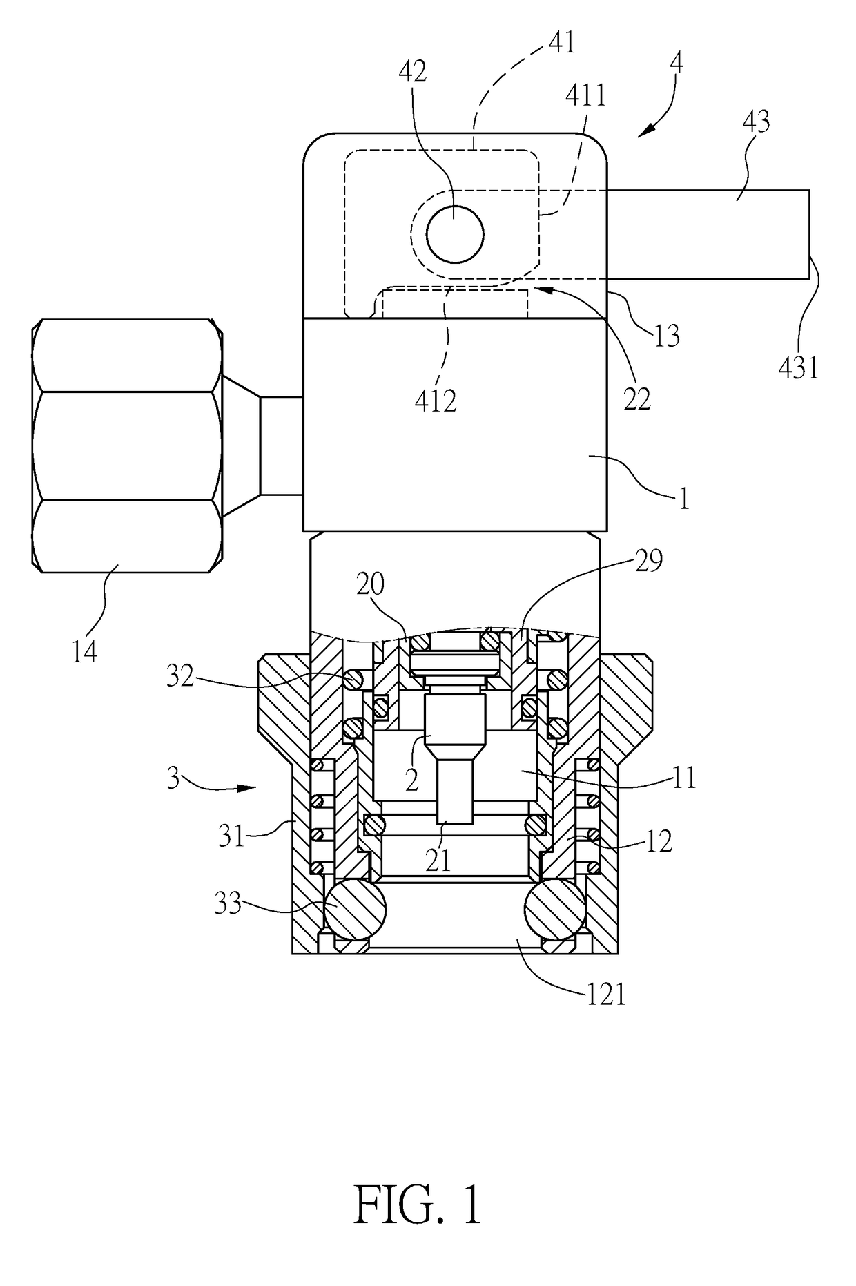
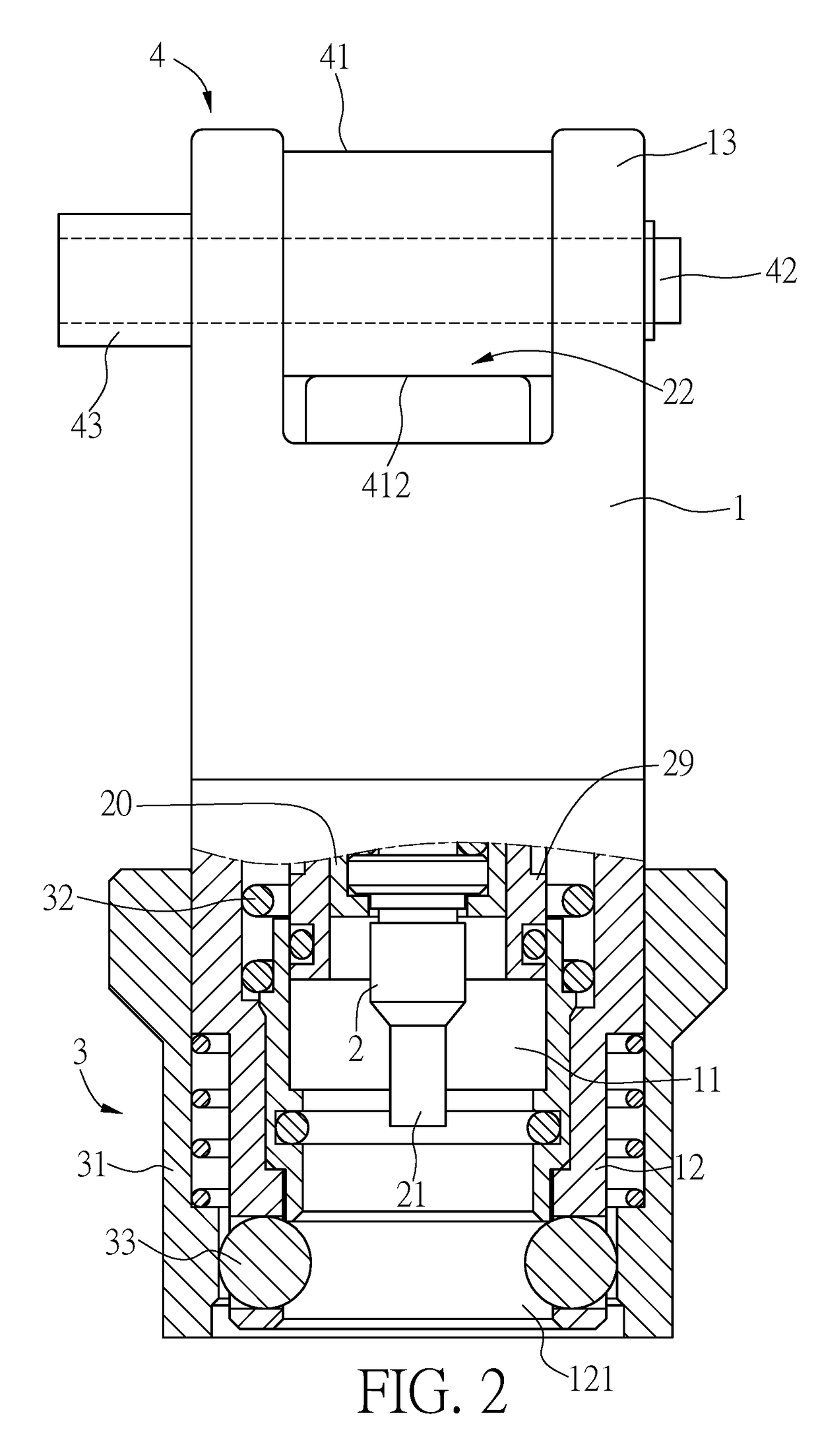
[0022]The present embodiment provides an adjustable connector which is configured to connect with a valve spout of a refrigerant pipe for refrigerant-stuffing. As shown in FIG. 1 to FIG. 3, the adjustable connector includes a body 1, a valve pin 2, a quick-release assembly 3 and a driving member 4.

[0023]As illustrated in FIG. 1 and FIG. 2, the body 1 has a cylindrical form with a chamber 11, and has a mounting part 12 and an installation part disposed at two ends ...


PUM


Abstract

An adjustable connector for refrigerant pipe includes a body, a valve pin is inserted into the body, and the body includes a quick-release assembly and a driving member respectively disposed on a mounting part and an installation part thereof. When the driving member is operated to suppress the pressed end of the valve pin to move the pushing end close to the pocket, the valve spout is opened to pass the refrigerant. Besides, when the driving member is operated to not suppress the pressed end by jumping off itself quickly, the pushing end is moved away from the pocket, so that the valve spout is closed to block the refrigerant.

Description

TECHNICAL FIELD[0001]The present disclosure relates to an adjustable connector, more particularly to a connector which is applied to connect a valve spout of a refrigerant pipe for refrigerant-stuffing.RELATED ART[0002]Please refer to FIG. 9, which is a conventional connector for connecting with a valve spout of a refrigerant pipe. In the connector, a body 91 has a mounting part 92 disposed at one end thereof and configured to mount the valve spout 93, and has one knob 94 disposed at the other end thereof, where the knob 94 is linked to a valve pin 95 which is inserted into the body 91. By manner of rotating the button 94 to move the valve pin 95 towards the valve spout 93, a thimble 96 inside the valve spout 93 is pushed by the valve pin 95, so as to stuff the refrigerant pipe with the refrigerant. After refrigerant-stuffing is completed, the knob 94 is rotated in an opposite direction to release the push of the valve pin 95 against the punch pin 96, so as to block communication be...

Claims


Application Information

Patent Timeline
IPC IPC(8): F16K31/50F16L37/23F16K1/30F16K31/56
CPCF16K31/508F16K1/302Y10T137/87965Y10T137/87949F16L37/23F16K31/566F16L37/40
Inventor CHIU, SHENG YUNG
Owner CHIU SHENG YUNG
Why Eureka
Try Eureka