Reactive power compensation system and method thereof

a compensation system and reactive power technology, applied in the field of reactive power compensation system, can solve the problems of inability to accurately and efficiently compensate reactive power, and part of power loss

Inactive Publication Date: 2017-11-30
LSIS CO LTD
View PDF7 Cites 3 Cited by
  • Summary
  • Abstract
  • Description
  • Claims
  • Application Information

AI Technical Summary

Benefits of technology

[0009]Objects of the present disclosure are not limited to the above-described objects and other objects and advantages can be appreciated by those skilled in the art from the following descriptions. Further, it will be easily appreciated that the objects and advantages of the present disclosure can be practiced by means recited in the appended claims and a combination thereof.
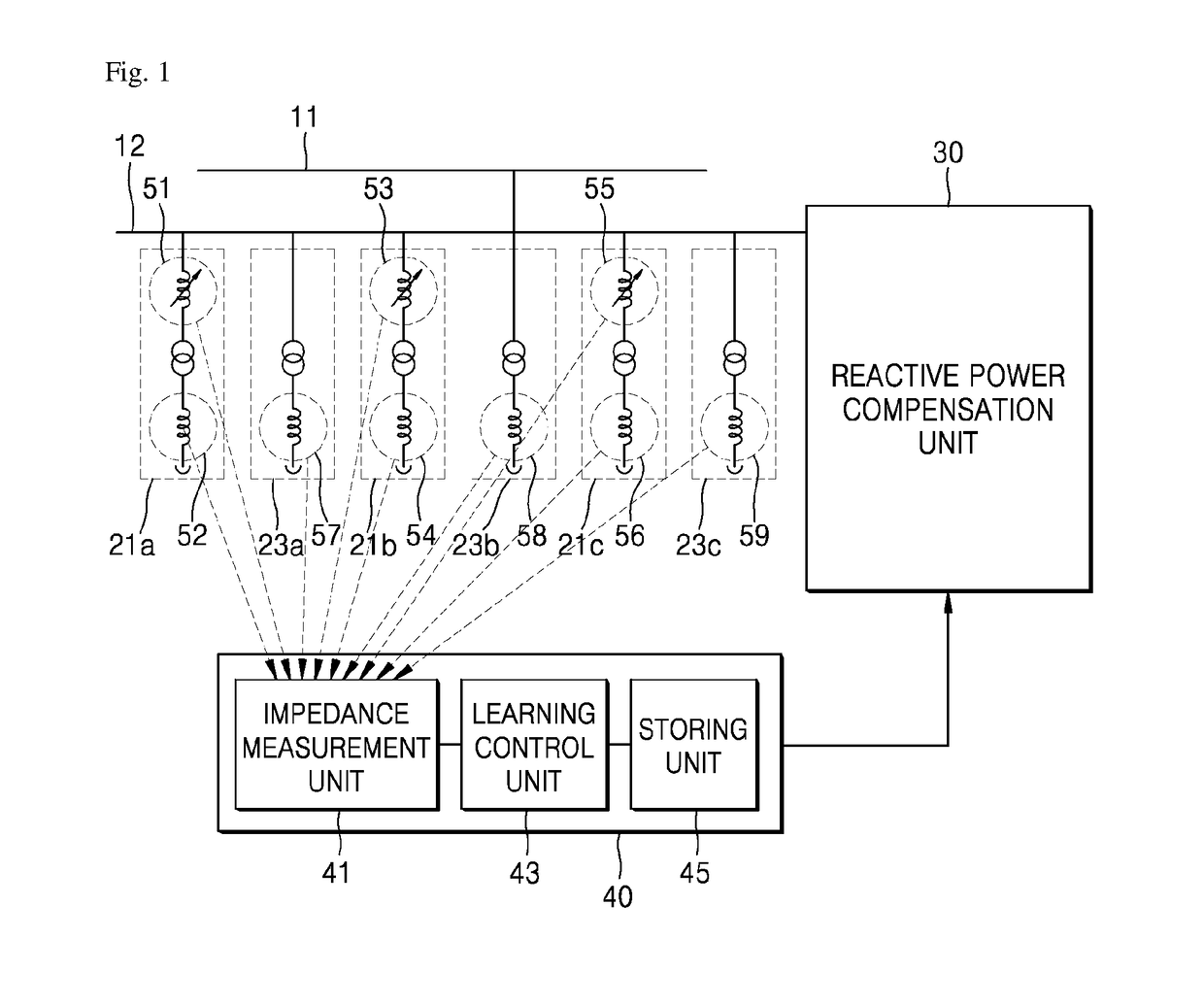
[0010]In accordance with one aspect of the present disclosure, a system for compensating reactive power includes a reactive power compensation unit for measuring compensate reactive power, an impedance measurement unit for measuring an impedance value of each of a plurality of loads, and a learning control unit for controlling the reactive power compensation unit based on the measured impedance value.
[0011]In accordance with one aspect of the present disclosure, a method of compensating reactive power includes measuring an impedance value of each of a plurality of loads, monitoring an impedance change amount according to according to a loading state of each of the loads or an environmental change, determining an optimal control mode based on a monitored impedance change amount, and generating a control signal to compensate reactive power according to a determined optimal control mode.

Problems solved by technology

In other words, the power is not all used as active power by the load and part of the power is lost as reactive power not contributing to a real work.
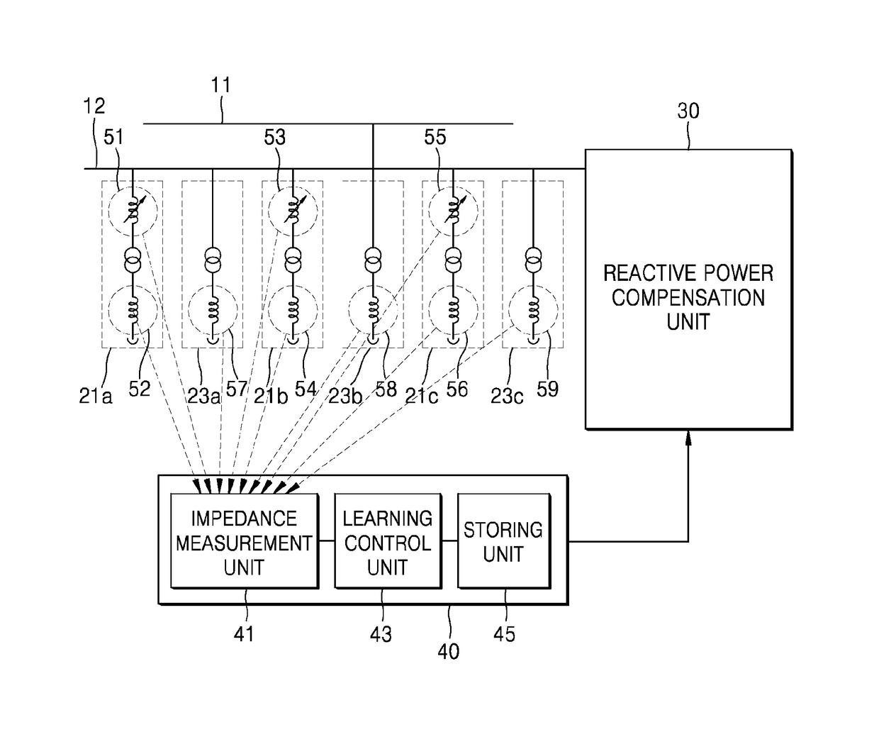
However, in a conventional reactive power compensation system, since the reactive power is simply compensated without considering a loading state of each of the loads 21a, 21b, 21c, 23a, 23b, and 23c or an environmental change, accurate and efficient compensation of reactive power is impossible.

Method used


Image

  • Reactive power compensation system and method thereof
  • Reactive power compensation system and method thereof
  • Reactive power compensation system and method thereof

Examples


Embodiment Construction

[0015]The above objects, features and advantages will become apparent from the detailed description with reference to the accompanying drawings. Embodiments are described in sufficient detail to enable those skilled in the art in the art to easily practice the technical idea of the present disclosure. Detailed descriptions of well-known functions or configurations may be omitted in order not to unnecessarily obscure the gist of the present disclosure. Hereinafter, embodiments of the present disclosure will be described in detail with reference to the accompanying drawings. Throughout the drawings, like reference numerals refer to like elements.

[0016]As the inventive concept allows for various changes and numerous embodiments, particular embodiments will be illustrated in the drawings and described in detail in the written description, wherein like reference numerals in the drawings denote like elements, and thus their description will not be repeated. The suffix “module” and “unit” ...


PUM


Abstract

The present disclosure relates to a reactive power compensation system including a reactive power compensation unit for measuring compensate reactive power, an impedance measurement unit for measuring an impedance value of each of a plurality of loads, and a learning control unit for controlling the reactive power compensation unit based on the measured impedance value.

Description

CROSS-REFERENCE TO RELATED APPLICATIONS[0001]This application claims the priority of Korean Patent Application No. 10-2016-0067076 filed on May 31, 2016, in the Korean Intellectual Property Office, the disclosure of which is hereby incorporated by reference in its entirety.BACKGROUND1. Technical Field[0002]The present disclosure relates to a reactive power compensation system and a method thereof.2. Description of the Related Art[0003]When power is supplied to a receiving end connected to a load, the power is not all used by the load. In other words, the power is not all used as active power by the load and part of the power is lost as reactive power not contributing to a real work.[0004]To minimize or compensate the reactive power, a reactive power compensation system is employed.[0005]The reactive power compensation system adjusts a phase of a voltage or a phase of current and thus the reactive power may be minimized[0006]However, in a conventional reactive power compensation syst...

Claims


Application Information

Patent Timeline
Patent Type & Authority Applications(United States)
IPC IPC(8): G05F1/70
CPCG05F1/70H02J3/1821H02J3/01H02J3/16H02J3/18H02J3/26H02J3/002Y02E40/30Y02E40/40Y02E40/50H02J3/1842
Inventor CHOI, YONG-KIL
Owner LSIS CO LTD
Why Eureka
Try Eureka