Broadband filtering compensation transformer
A compensating transformer and broadband technology, applied in the field of transformers, can solve problems such as affecting the working performance, unable to compensate the reactive power of the network, and the transformer cannot effectively eliminate the high-order harmonics of the power grid, so as to achieve reasonable structure, compensation for reactive power, elimination of The effect of higher harmonics
Inactive Publication Date: 2012-12-19
JIANGSU DONGYUAN ELECTRIC APPLIANCEGROUP
View PDF3 Cites 0 Cited by
- Summary
- Abstract
- Description
- Claims
- Application Information
AI Technical Summary
Problems solved by technology
[0002] The existing transformers cannot effectively eliminate the higher harmonics of the power grid, and cannot compensate the reactive power of the network, which affects the working performance
Method used
View moreImage
Smart ImageViewing Examples
Examples
Embodiment Construction
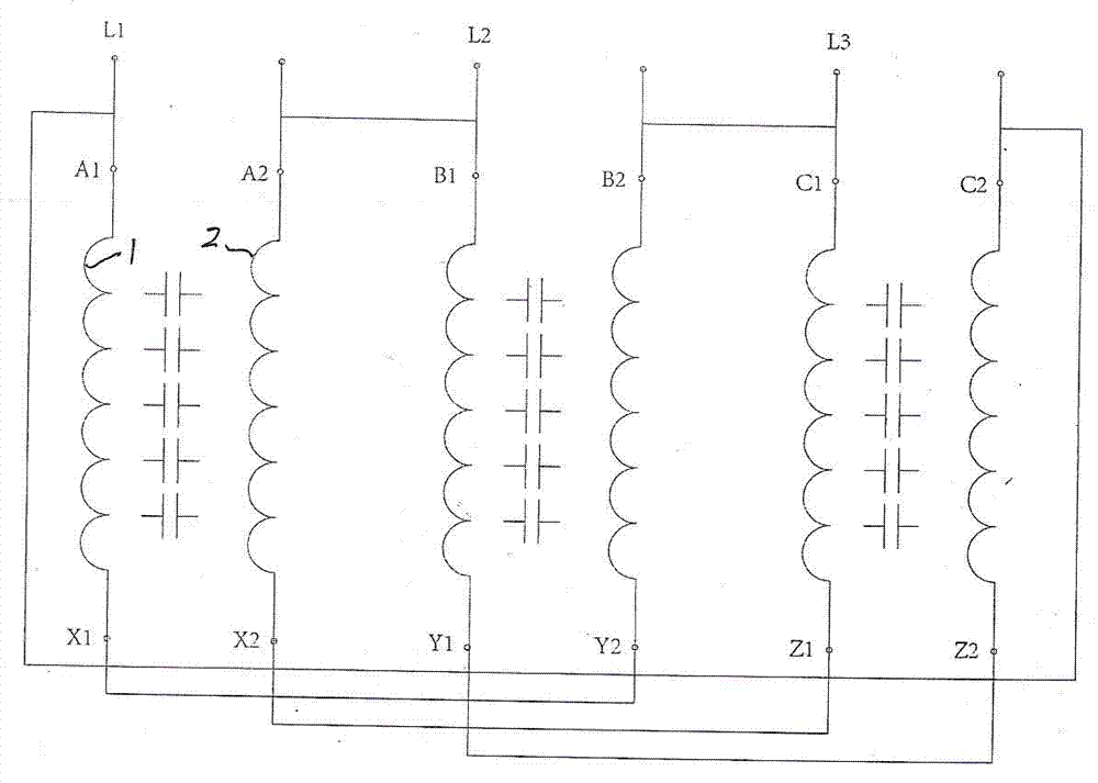
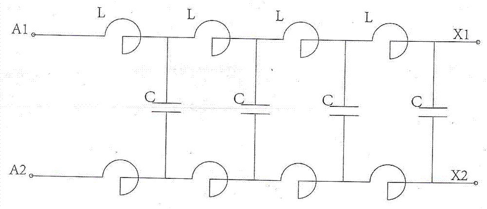
[0011] A wide-band filter compensation transformer, each of the three phases of the transformer adopts two layers of mutually insulated foil windings 1 and 2, and the two layers of mutually insulated foil windings are also the two plates of the capacitor. A high voltage difference is formed between the windings, and a broadband LC filter absorption loop is formed.
Login to View More PUM
 Abstract
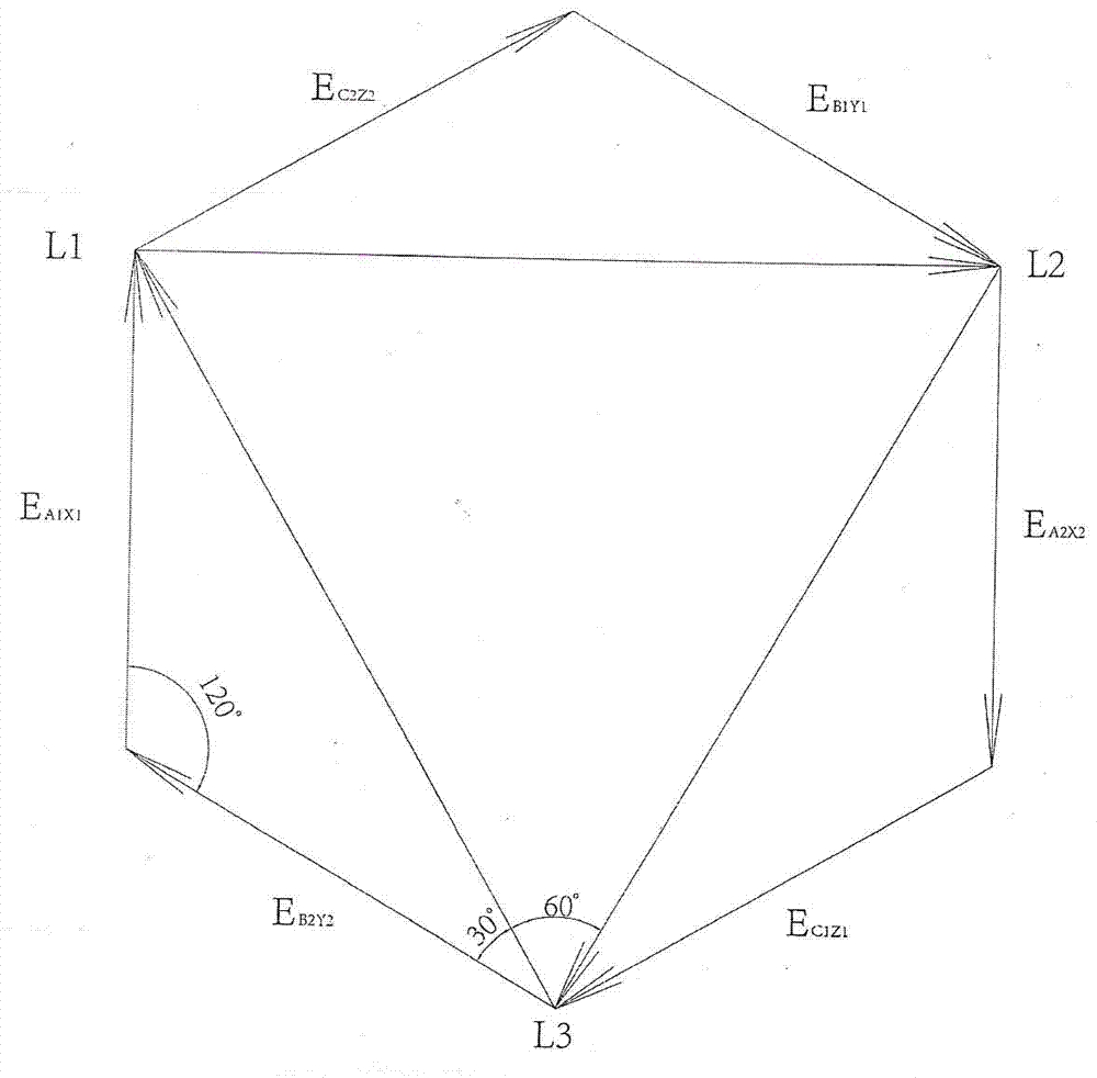
The invention discloses a broadband filtering compensation transformer, wherein each of three phases of the transformer adopts two layers of foil windings which are insulated from each other, the two layers of foil windings which are insulated from each other are also two polar plates of a capacitor, voltage difference is generated between the two windings through a wiring mode, and a broadband inductance and capacitance (LC) filtering absorption circuit is formed. The broadband filtering compensation transformer is reasonable in design, the broadband LC filtering absorption circuit is formed, the higher harmonic of a power grid is effectively eliminated, and the reactive power of a network is compensated.
Description
technical field [0001] The invention relates to a transformer. Background technique [0002] The existing transformers cannot effectively eliminate the high-order harmonics of the power grid, and cannot compensate the reactive power of the network, which affects the working performance. Contents of the invention [0003] The object of the present invention is to provide a wide-band filter compensation transformer with reasonable structure and good working performance. [0004] Technical solution of the present invention is: [0005] A wide-band filter compensation transformer, characterized in that: each of the three phases of the transformer adopts two layers of mutually insulated foil windings, and the two layers of mutually insulated foil windings are also two pole plates of the capacitor. A voltage difference is formed between the two windings, and a broadband LC filter absorption circuit is formed. [0006] The invention has a reasonable structure, forms an LC filt...
Claims
Login to View More Application Information
Patent Timeline
 Patent Type & Authority Applications(China)
IPC IPC(8): H01F30/12H01F27/28H02J3/01H02J3/18
CPCY02E40/30Y02E40/40
Inventor 孙益源邱卫东孙志忠
Owner JIANGSU DONGYUAN ELECTRIC APPLIANCEGROUP
Features
- R&D
- Intellectual Property
- Life Sciences
- Materials
- Tech Scout
- Unparalleled Data Quality
- Higher Quality Content
- 60% Fewer Hallucinations
Learn More Browse by: Latest US Patents, China's latest patents, Technical Efficacy Thesaurus, Application Domain, Technology Topic, Popular Technical Reports.
© 2025 PatSnap. All rights reserved.Legal|Privacy policy|Modern Slavery Act Transparency Statement|Sitemap|About US| Contact US: help@patsnap.com


