Amplification circuit

Active Publication Date: 2017-11-30
SK HYNIX INC
View PDF2 Cites 1 Cited by
  • Summary
  • Abstract
  • Description
  • Claims
  • Application Information

AI Technical Summary

Benefits of technology

[0026]The amplification block may further include: a first switching unit suitable for selectively coupling an input node of the second amplification unit, where the second voltage is inputted, to an output node of the first amplification unit, where the first amplification signal is outputted, in response to the first control signal; a second switching unit suitable for selectively coupling an input node of the first amplification unit, where the first input voltage is inputted, to an output node of the second amplification unit, where the second amplification signal is outputted, in response to the first control signal; a third switching unit suitable for selectively supplying the supply voltage to the first amplification unit in response to the second control signal; a fourth switching unit suitable for selectively supplying the supply voltage to the second amplification unit in response to the second control signal; a first initialization unit suitable for initializing the output node of the first amplification unit by a predetermined voltage based on the second control signal; and a second initialization unit suitable for initializing the output node of the second amplification unit by the predetermined voltage based on the second control signal.
[0027]The second amplific

Problems solved by technology

However, the latch-type amplifier may not output an intended amplification result due to an offset mainly caused by variations in device characteristics such as transistor charac

Method used


Image

  • Amplification circuit
  • Amplification circuit
  • Amplification circuit

Examples


Example

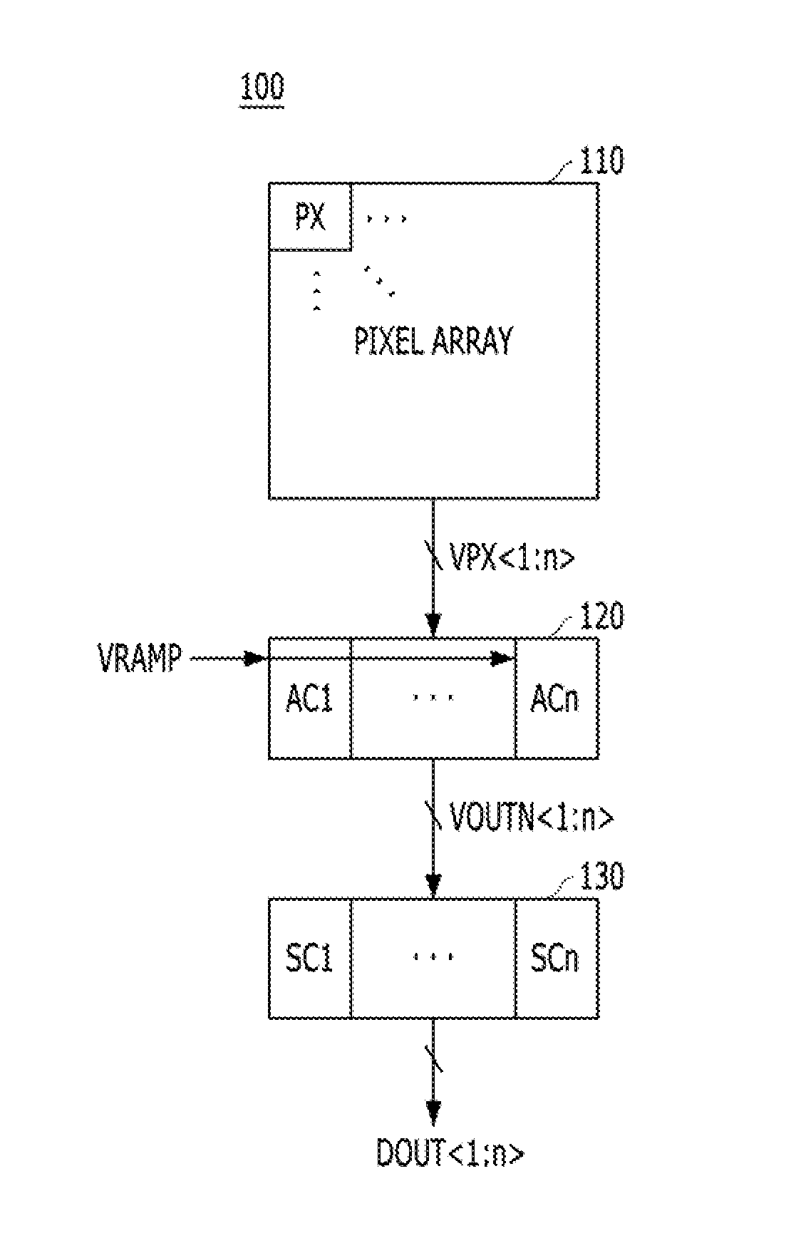
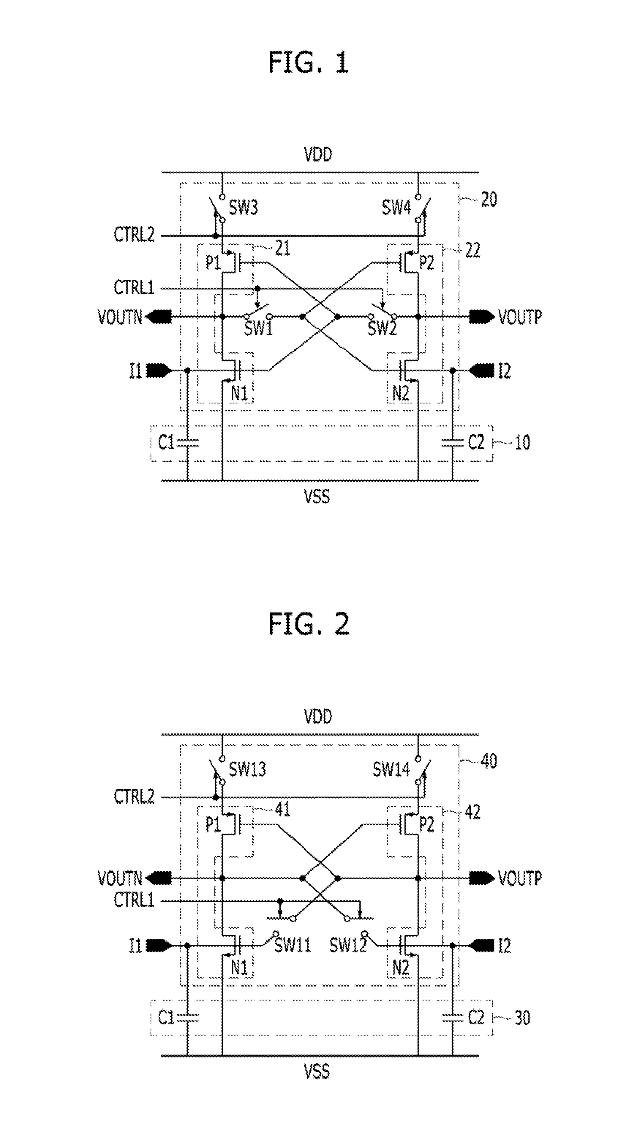
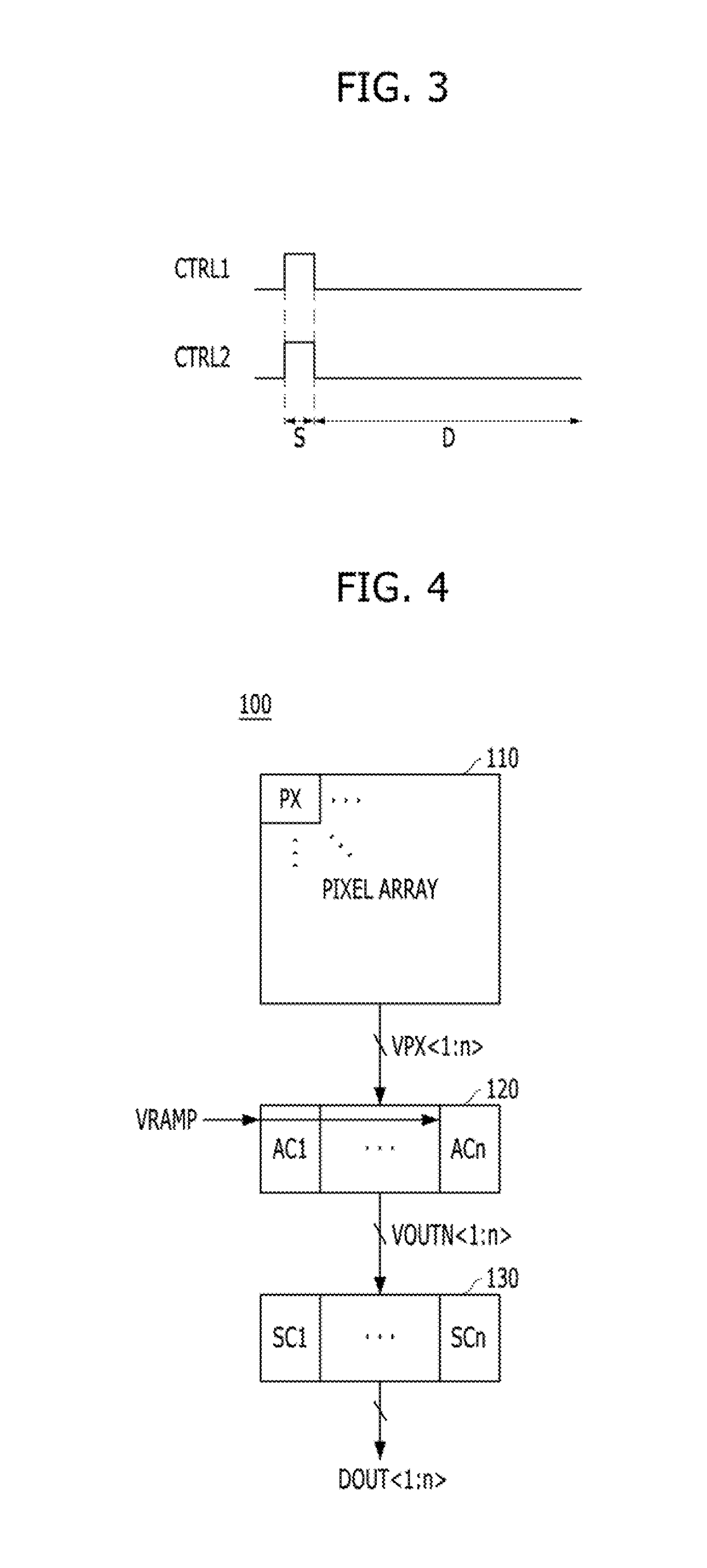
[0036]Various embodiments of the present invention will be described below in more detail with reference to the accompanying drawings. These embodiments are provided so that this disclosure is thorough and complete. All “embodiments” referred to in this disclosure refer to embodiments of the inventive concept disclosed herein. The embodiments presented are merely examples of the invention and are not intended to limit the scope of the invention.

[0037]Moreover, it is noted that the terminology used herein is for the purpose of describing the embodiments only and is not intended to be limiting of the invention. As used herein, singular forms are intended to include the plural forms as well, unless the context clearly indicates otherwise. It will be further understood that the terms “comprises,”“comprising,”“Includes,” and / or “including” when used in this specification, indicate the presence of stated features, but do not preclude the presence or addition of one or more other non-state...


PUM


Abstract

An amplification circuit includes a first amplification block suitable for primarily amplifying a voltage difference between a first voltage and a second voltage corresponding to a first input current and a second input current, respectively, and a second amplification block suitable for secondarily amplifying the voltage difference between the first and second voltages to generate an amplification signal.

Description

CROSS-REFERENCE TO RELATED APPLICATIONS[0001]The present application claims priority under 35 U.S.C 119(a) to Korean Patent Application No. 10-2016-0066308, flied on May 30, 2016, which is incorporated herein by reference in its entirety.BACKGROUND1. Field[0002]Various embodiments of the present invention relate generally to a design technology of an integrated circuit and, more particularly, to an amplification circuit, a method for driving the same, and an image sensing device including the amplification circuit.2. Description of the Related Art[0003]Generally, integrated circuits are required to operate at higher speeds and consume less current. For improving the performance of integrated circuits, sensing and amplifying valid data, which includes comparing data with a reference value, has become an essential operating process of the integrated circuits.[0004]Generally, in an integrated circuit, an amplification circuit may function as a comparator. The comparator compares a volt...

Claims


Application Information

Patent Timeline
IPC IPC(8): H04N5/378H03F3/217
CPCH03F3/2171H04N5/378G09G3/00H04N25/75H03F3/16H04N5/32H01L27/14609H01L27/14658H04N25/77
Inventor KIM, TAE-GYU
Owner SK HYNIX INC
Why Eureka
Try Eureka