
Transportable and stackable server racks

a server rack and stacking technology, applied in the field of server racks, can solve the problems of high center of gravity of server racks, affecting the safety of storage racks, affecting the safety of storage racks, etc., and achieve the effects of facilitating storage racks, safe transportation, and safe stacking

Active Publication Date: 2017-12-14
OVH
View PDF21 Cites 19 Cited by
  • Summary
  • Abstract
  • Description
  • Claims
  • Application Information

AI Technical Summary

Benefits of technology

The patent text describes server racks that can be transported and stacked in the most efficient and secured ways. These racks can be easily transported using conventional means like vehicles or pallet lifting devices. The text also highlights that the server racks have a structure / frame that minimizes transport difficulties and works closely with load-handling apparatus. Overall, the patent aims to provide a solution to improve the overall efficiency and safety of server racks in transportation and stacking.

Problems solved by technology

Particular attention should be paid during the transportation of such fragile and complex hardware because of the inconvenient and inappropriate structure of current server racks for such operation.
Server racks, which have a high center of gravity, can fall over during their transportation.
This problem may arise during, as non-limiting examples,during sudden bracking or when driving up or down a ramp;during takeoff or landing, when the server rack is transported by a plane;during vibration, when the sever rack is transported by a boat.
Moreover, when increasing the total number of units U to be housed in the server rack and / or when profiting entirely of the useful height of the server rack, its gravity center moves further up and compromises its transportation.
As a further problem, the safety of operators, and surrounding objects are also concerned.
A server rack may weigh several hundred kilograms which cannot be easily handled.
It should also be noted that current server racks are not suitable to be stacked and, consequently, the space thereabove is usually unused.
Current server racks are not provided with means permitting to achieve such arrangement.
Accordingly, because of their structure and typically their vertically elongated form, whether the transportation or the stacking of existing server racks is challenging.

Method used


Image

  • Transportable and stackable server racks
  • Transportable and stackable server racks
  • Transportable and stackable server racks

Examples


Embodiment Construction

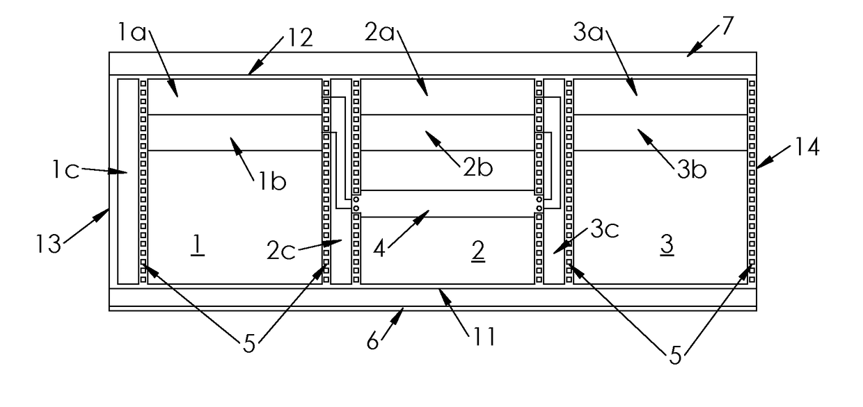
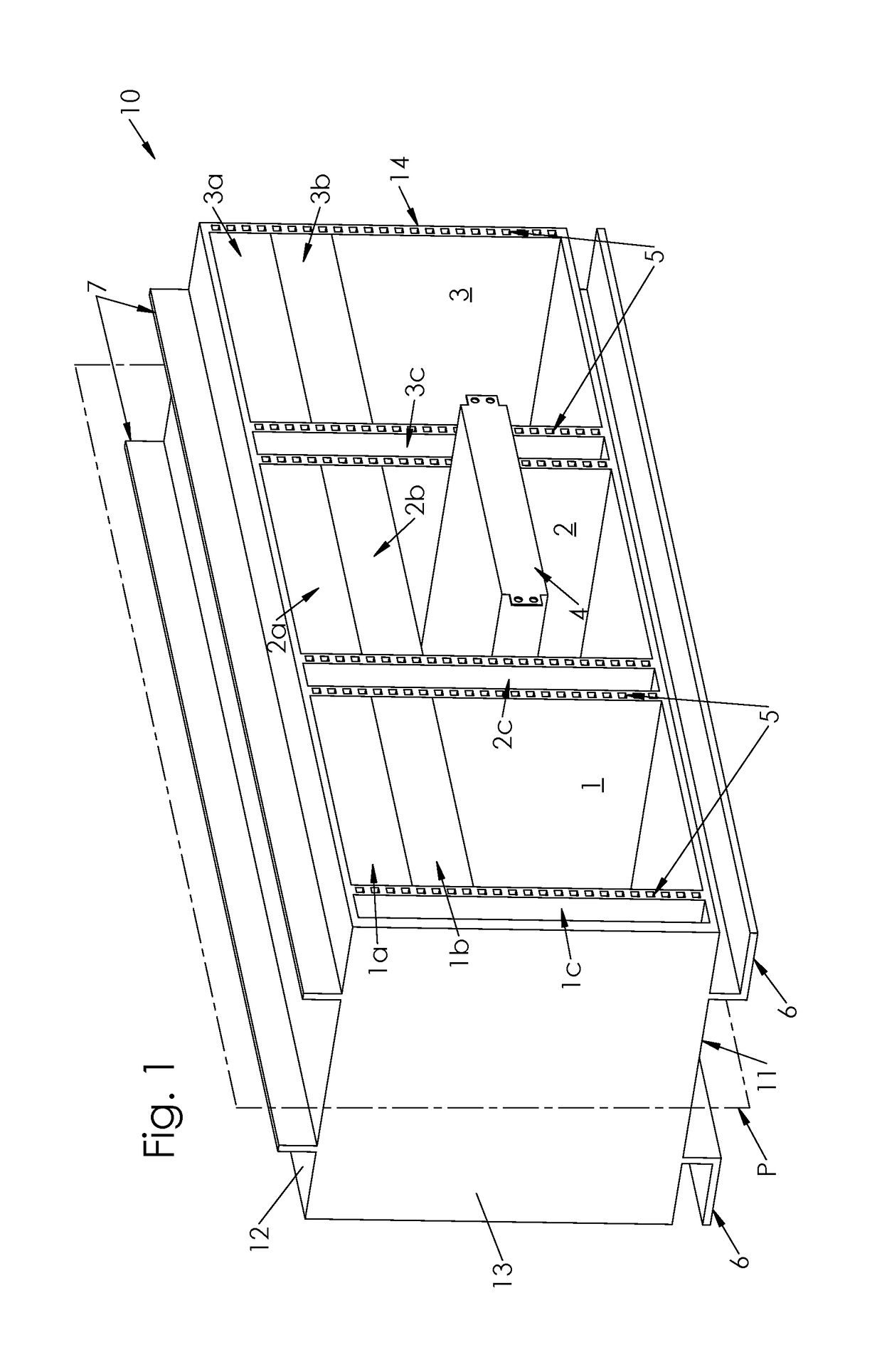
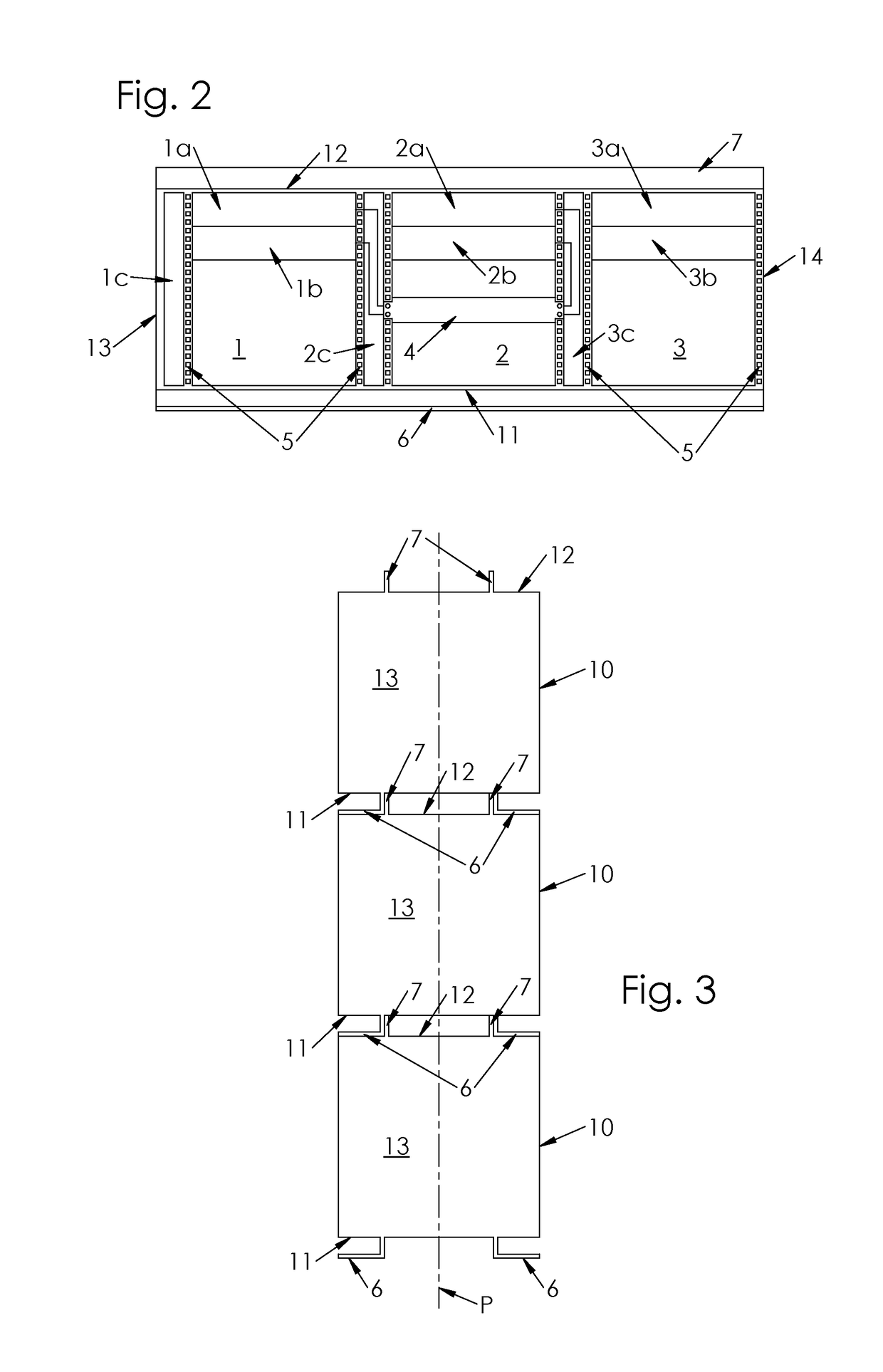
[0051]With reference to FIG. 1, there is shown a server rack 10 including a plurality of housing units 1-3. These housing units 1-3 are configured to receive / house rack-mountable equipment 4 such as servers, switches or routers.

[0052]The server rack 10 includes a bottom panel 11, a top panel 12 opposite to the bottom panel 11, and two side panels 13-14. In one embodiment, the server rack further includes a back panel (not represented). Moreover, housing units 1-3 may be provided or not with doors (constituting a front panel). Appropriate fastening means permit the assembly of these panels 11-14 to obtain the frame of the server rack 10.

[0053]In one embodiment, air vents and / or fans may be designed in the sides panels 13-14, the top panel 12, the bottom panels 11 and / or the back panel (not represented), so as to move cooling air in specified direction and rate.

[0054]Housing units 1-3 are arranged horizontally side-by-side between the top panel 12 and the bottom panel 11. More general...


PUM


Abstract

A server rack including a bottom panel, a top panel opposite to said bottom panel, a plurality of housing units configured for receiving rack-mountable equipment, the plurality of housing units being horizontally side-by-side arranged between the top panel and the bottom panel, the bottom panel comprising two support rails for supporting the server rack.

Description

FIELD OF THE INVENTION[0001]The present invention pertains to server racks, and more specifically to transportable and stackable server racks.BACKGROUND OF THE INVENTION[0002]As used herein, the term server rack is meant broadly and not restrictively, to include any structure or frame configured to simultaneously house multiple data processing equipment such as servers, switches, routers, or similar devices that comply with the server rack mounting space. Server racks, also known as computer rack, or server / computer cabinet (when fitted with doors and usually side panels which might be removable), are generally used in data centers or network rooms.[0003]With the spread of information and communication technologies throughout the world, data center operators may have to manage a plurality of data centers located in different geographical locations such as in different buildings, towns, countries, or even continents.[0004]So as to fill, update, or meet specific needs, a data center o...

Claims


Application Information

Patent Timeline
Patent Type & Authority Applications(United States)
IPC IPC(8): H05K7/18H05K7/14B60B33/06
CPCH05K7/183H05K7/1491H05K7/1489B60B33/063H05K7/1488H05K2201/10515A47B87/0276H05K7/023H05K5/0234H05K5/0021A47B2210/0051A47B87/0292H05K5/0247A47B87/0284
Inventor KLABA, MIROSLAWKLABA, HENRI
Owner OVH
Learn More