Multiphase device and system for heating, condensing, mixing, deaerating and pumping

a multi-phase device and pumping technology, applied in the direction of corrosion-reducing boiler components, machines/engines, transportation and packaging, etc., can solve the problems of substantial electric, heat and water loss, sewer discharge rate, deaerators cannot provide the large heating, condensing and deaerating capacity, and deaerators experience water hammer

Inactive Publication Date: 2017-12-21
KREMER ROBERT
View PDF0 Cites 4 Cited by
  • Summary
  • Abstract
  • Description
  • Claims
  • Application Information

AI Technical Summary

Problems solved by technology

Such systems operate with substantial electric, heat and water losses and sewer discharge rate.
At these conditions the deaerators cannot provide the large heating, condensing and deaerating capacity.
As a result of these conditions the deaerators experience water hammer and deteriorated heating and deaeration performance.
This causes intensive corrosion of the power plant equipment and district steam piping.
This system requires large expensive heat exchangers and electric driven pumps.
The tubing system of the heat exchangers is also subject to intensive corrosion caused by the released non-condensable gases.
Because heat exchangers use indirect heat transfer through surfaces, they become plugged with scaling causing the reduction of heat transfer and efficiency.

Method used


Image

  • Multiphase device and system for heating, condensing, mixing, deaerating and pumping
  • Multiphase device and system for heating, condensing, mixing, deaerating and pumping
  • Multiphase device and system for heating, condensing, mixing, deaerating and pumping

Examples


embodiment 1

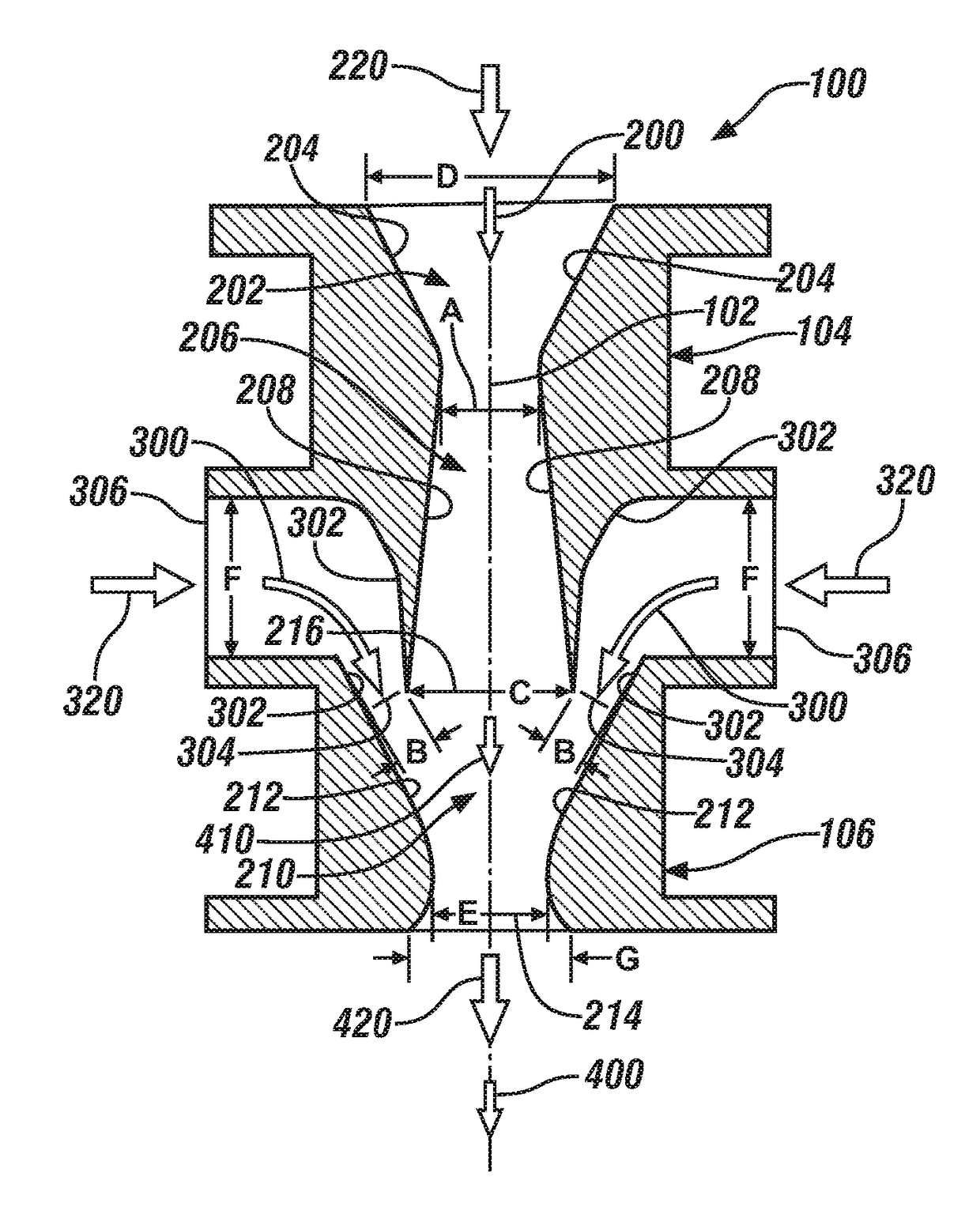
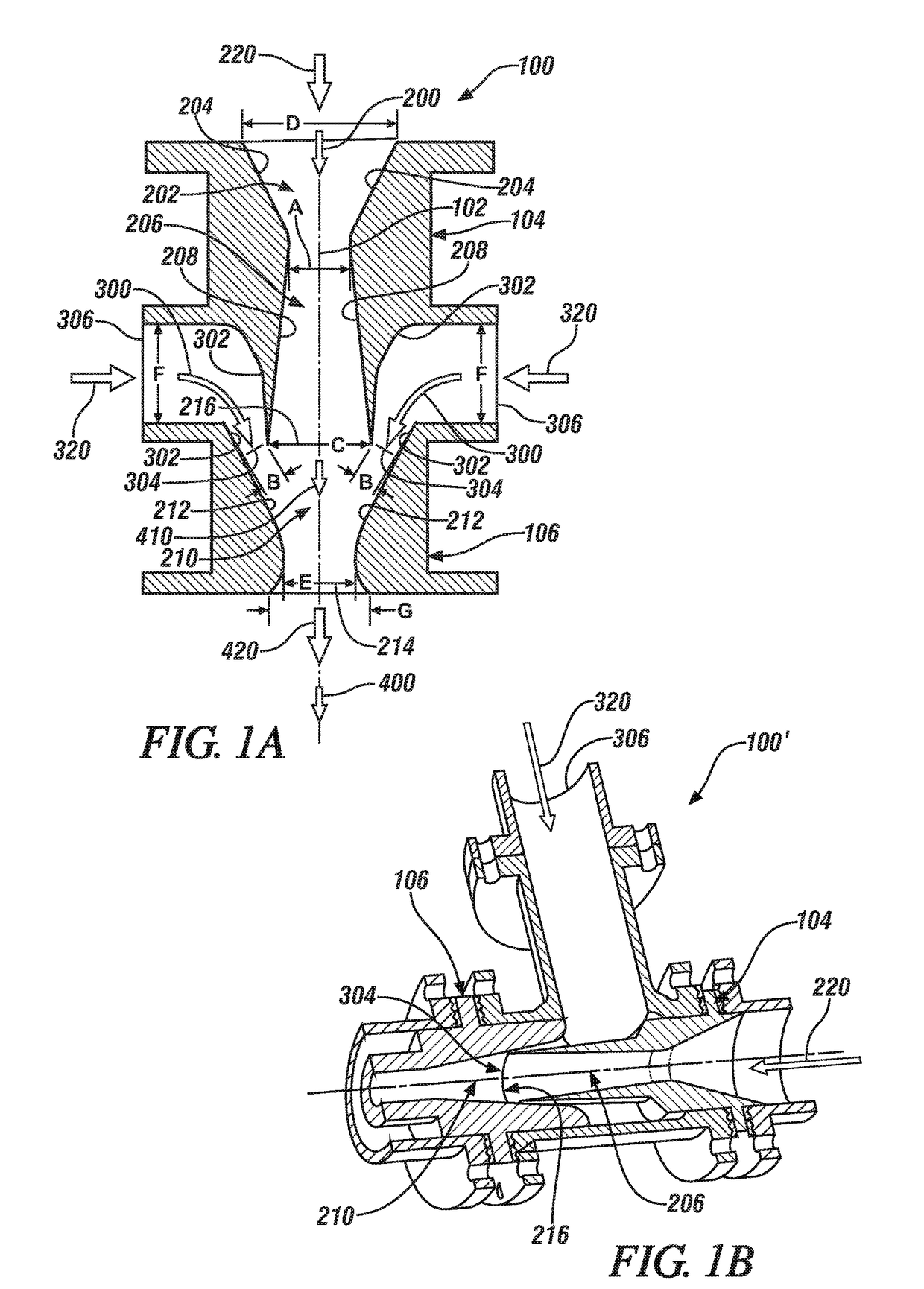
[0051 includes a device in the form of a green (environmentally friendly) two-phase direct contact deaerator device having round, square, triangular, or elliptically shaped gas, liquid, two-phase or steam nozzles for heating, condensing, deaerating and pumping liquids, particularly water.

[0052]Embodiment 2 includes the device according to Embodiment 1, further including single or multiple inlets for gas, steam, two-phase fluids or liquids.

embodiment 3

[0053 includes the device according to any of Embodiments 1-2, further including an arrangement where an inlet nozzle, or nozzles are aligned with a mixing nozzle or nozzles.

embodiment 4

[0054 includes the device according to any of Embodiments 1-3, further including a mixing section, or sections where the gas or steam are mixed with liquids at supersonic velocity.

[0055]Embodiment 5 includes the device according to any of Embodiments 1-4, further having condensed the gas or steam and heated the liquid to a determined temperature, wherein the non-condensable gases are released from the liquid in the form of bubbles.


PUM

PropertyMeasurementUnit
pressureaaaaaaaaaa
flow forceaaaaaaaaaa
velocityaaaaaaaaaa

Abstract

An energy saving deaerator device includes: a first incoming flow path that generally follows a central axis of the device from a conically shaped inlet having converging sidewalls, to an expansion chamber having diverging sidewalls, to a compression chamber having converging sidewalls, to an outlet, a first entry port of the compression chamber being defined by an outlet of the expansion chamber; a second incoming flow path having sidewalls that converge to form a ring shaped second entry port of the compression chamber, the ring shaped second entry port being disposed around and concentric with the first entry port; and, wherein the first and second incoming flow paths converge at the compression chamber, with both flow paths being directed toward the outlet, to form an outgoing flow path.

Description

BACKGROUND OF THE INVENTION[0001]The subject matter disclosed herein relates to green (environmentally friendly) thermal, chemical and mechanical engineering and in particular to direct contact reactors, heat exchangers, mixing various gases, vapors and fluids, producing heat, energy recovery, condensing vapors, deaerating and pumping fluids and liquids.[0002]Many utilities in the United States and around the world generate and supply district steam to buildings for space heating, cooling and domestic hot water purposes. The steam condensate is sometimes returned to the steam generating source or discharged to the city sewer system. In order to reduce the condensate temperature from 220 F to about 140 F (the city sewer requirement) the condensate is mixed with cold potable water. Such systems operate with substantial electric, heat and water losses and sewer discharge rate. The lost condensate must be made-up at the power or boiler plants with cold demineralized water treated in typ...

Claims


Application Information

Patent Timeline
Patent Type & Authority Applications(United States)
IPC IPC(8): B01F5/04B01F3/04B01F23/80
CPCB01F5/0413B01F3/04985B01F3/0446B01F23/232B01F23/29B01F25/31432F01K9/02F01K19/08F22B37/025Y02E20/14F04F5/10F04F5/16F04F5/24B01F25/3122B01F23/803F04F5/00B01F25/312
Inventor KREMER, ROBERT
Owner KREMER ROBERT
Why Eureka
Try Eureka