Method for manufacturing plastic window and plastic window

Active Publication Date: 2017-12-21
TOYOTA IND CORP
View PDF0 Cites 1 Cited by
  • Summary
  • Abstract
  • Description
  • Claims
  • Application Information

AI Technical Summary

Benefits of technology

The present invention provides a method for manufacturing a plastic window with a cover and a functional film that can be thermally deformed. The method includes preparing a first mold, a second mold, and a third mold, and preparing a functional film with a conductive portion and a bus bar. The functional film is then placed on the first mold, and a first injection step is performed to form the cover. A second injection step is then performed to form the transparent body. The method allows for the efficient manufacturing of plastic windows with improved functional film integration.

Problems solved by technology

However, it is difficult to provide a conductive part and a bus bar on a curved transparent body.
In such a plastic window, however, the exposure of the bus bar on the second surface side of the transparent body degrades the appearance of the plastic window.
In order to prevent the exposure of the bus bar, an opaque cover may be provided on the second surface, or alternatively an additional step for coloring the transparent body with opaque color may be performed, which only results in difficulty in the manufacture of the plastic window and hence in increased production cost.

Method used


Image

  • Method for manufacturing plastic window and plastic window
  • Method for manufacturing plastic window and plastic window
  • Method for manufacturing plastic window and plastic window

Examples


first embodiment

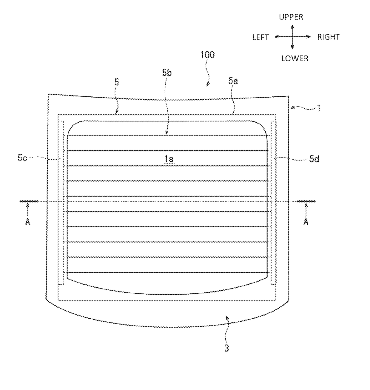
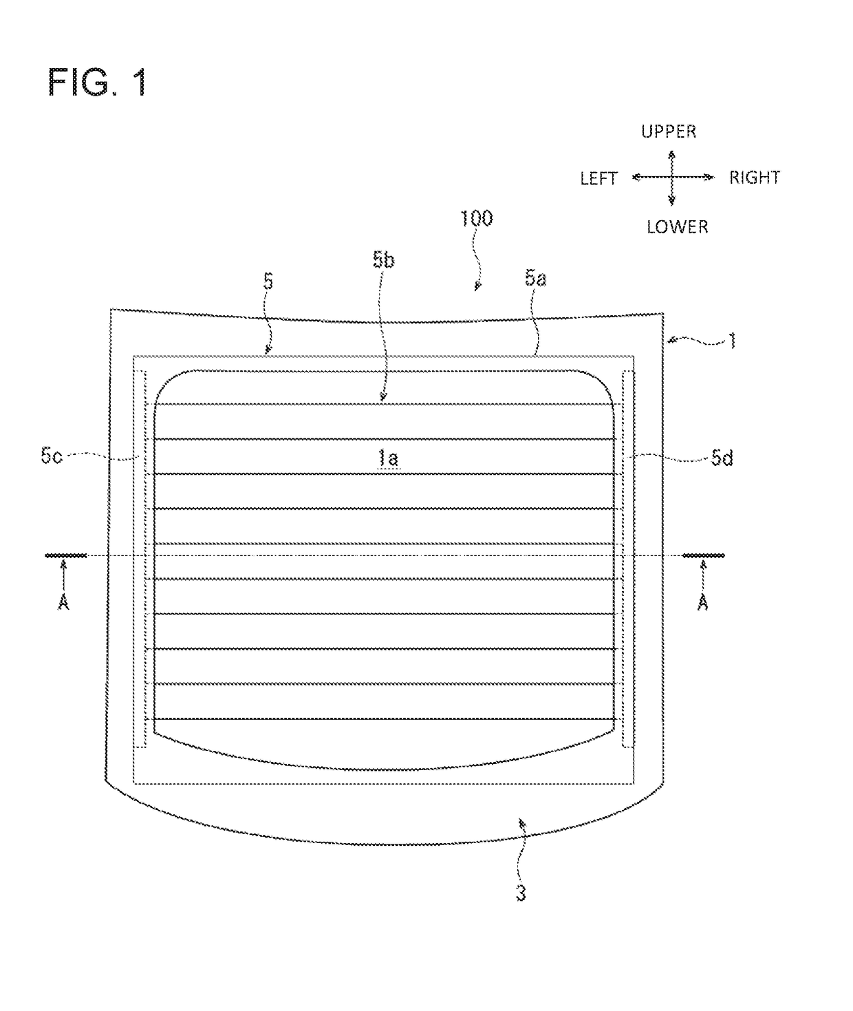
[0043]Referring to FIG. 1, a plastic window 100 according to the first embodiment includes a transparent body 1, a cover 3, and a functional film 5. The plastic window 100 is of a type that is mounted to a vehicle not shown. In the present embodiment, arrows shown in FIG. 1 denote the right, left, front, and rear directions of the plastic window 100, respectively. Left and right directions are perpendicular to front and rear directions. The same is true for the drawings having a similar directional notation. In FIGS. 2, 12, and 22, arrows with interior and exterior indicate the inside and outside of the vehicle, respectively, when the plastic window 100 or plastic windows 200, 300 which will be described later is mounted to a vehicle. These directions will be used for the sake of the description.

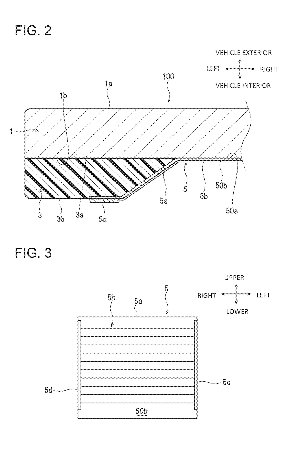
[0044]As shown in FIG. 2, the transparent body 1 is substantially of a rectangular flat plate shape and has on the opposite sides thereof a first surface 1a and a second surface 1b. The firs...

second embodiment

[0064]The following will describe a method for manufacturing a plastic window according to a second embodiment of the present invention with reference to FIGS. 9 and 10. The second embodiment differs from the first embodiment in that a functional film 51 shown in FIG. 9 is prepared instead of the functional film 5 used in the method according to the first embodiment. As with the functional film 5, the functional film 51 includes the base 5a and the conductive portion 5b formed on the back surface 50b of the base 5a. In the functional film 51, bus bar forming portions 5e, 5f are provided on the back surface 50b of the base 5a as shown by the imaginary line in FIG. 9. The bus bar forming portion 5e is located on the left side of the conductive portion 5b. The bus bar forming portion 5f is located on the right side of the conductive portion 5b. That is, in the film preparation step of the manufacturing method, the bus bars such as 5c and 5d are not formed on the functional film 51.

[006...

third embodiment

[0073]Referring to FIGS. 11 and 12, there is shown a plastic window 200 that is adapted to be mounted on a vehicle not shown and includes the transparent body 1 and the cover 3.

[0074]There is shown in FIGS. 13 and 14 a functional film 52 for the plastic window 200. As with the functional film 5 shown in FIG. 3, the functional film 52 includes the base 5a, the conductive portion 5b, and the bus bars 5c, 5d. The functional film 52 further includes colored portions 5g, 5h. As shown in FIG. 13, the conductive portion 5b and the bus bars 5c, 5d are formed on the back surface 50b of the base 5a. As shown in FIG. 14, the colored portions 5g, 5h are formed on the front surface 50a of the base 5a. The colored portions 5g, 5h are formed by providing black-colored opaque portions on the back surface 50b of the base 5a. The colored portion 5g is located at a position adjacent to the left end of the front surface 50a in an overlapping manner with the bus bar 5c and extends in the vertical direct...


PUM

PropertyMeasurementUnit
Electrical conductoraaaaaaaaaa
Transparencyaaaaaaaaaa

Abstract

A method for manufacturing a plastic window includes a mold preparation step for preparing a first mold, a second mold, and a third mold, a film preparation step for preparing a functional film, a conductive portion, and a bus bar, a placement step for placing the functional film, a first injection step, wherein an intermediate product provided with the cover on the functional film in an integral manner is made, and a second injection step, wherein a product provided with the intermediate product on the second surface in an integral manner is made. The first mold surface has a first forming portion forming the back surface of the cover and a second forming portion forming the second surface of the transparent body. In the placement step, the conductive portion is placed on the second forming portion and the bus bar is placed on the first forming portion.

Description

BACKGROUND OF THE INVENTION[0001]The present invention relates to a method for manufacturing a plastic window and a plastic window.[0002]Japanese Patent Application Publication No. H02-227224 discloses a conventional plastic window. The plastic window includes a transparent body, a film, and a frame. The transparent body is of a plate shape and has on the opposite sides thereof a first surface and a second surface. The transparent body is made of transparent resin. The film includes a transparent base having a sheet shape and a hard coating formed on the surface of the base. The film is provided on the first surface of the transparent body in an integral manner. The frame is made of resin and provided with the transparent body in an integral manner. The frame covers the end surface of the transparent body, the peripheral edge of the first surface of the transparent body including the peripheral edge of the film, and the peripheral edge of the second surface of the transparent body.[...

Claims


Application Information

Patent Timeline
IPC IPC(8): H05B3/86B29C45/16H05B1/02B29K69/00B29L31/30
CPCH05B3/86B29C45/1671H05B1/0236B29L2031/3052B29K2995/0025B29K2995/0026B29K2995/002B29K2069/00B29C45/14B29C45/1615B29C45/1642B29C45/2602B60J1/00B29C2045/1617B29L2031/30B29L2012/00B29K2995/0005B29L2031/779B29C45/14065B29C45/14811B29C45/1675B29C2045/14901B29C2045/14909H05B2203/011H05B2203/013H05B2203/017
Inventor TAKEMURA, KENJI
Owner TOYOTA IND CORP
Why Eureka
Try Eureka