
Anti-correlated noise filter

a noise filter and anti-correlated technology, applied in image data processing, instruments, computing, etc., can solve the problems of low-frequency noise filtering, noise introduction by imaging devices or scanners used to detect x-ray radiation and generate projection data, etc., to reduce or suppress anti-correlated noise, preserve structural and/or spectral aspects

Inactive Publication Date: 2017-12-28
KONINKLJIJKE PHILIPS NV
View PDF2 Cites 0 Cited by
  • Summary
  • Abstract
  • Description
  • Claims
  • Application Information

AI Technical Summary

Benefits of technology

The patent describes a method for reducing anti-correlated noise in image data sets. The method uses an iterative algorithm to jointly process the data sets to reduce or suppress the noise while preserving structural and spectral aspects. The method can be applied to both projection data sets and image data sets, and can be implemented using a computer program or computer system. The technical effect of the patent is to provide a more effective way to filter out noise in image data, which can improve the quality and accuracy of the image analysis and interpretation process.

Problems solved by technology

Particularly difficult is filtering low-frequency noise while preserving characteristics of the object or subject present at low- frequencies, such as real structures.
For example, the imaging device or scanner used to detect the x-ray radiation and generate the projection data introduces noise.

Method used


Image

  • Anti-correlated noise filter
  • Anti-correlated noise filter
  • Anti-correlated noise filter

Examples


Embodiment Construction

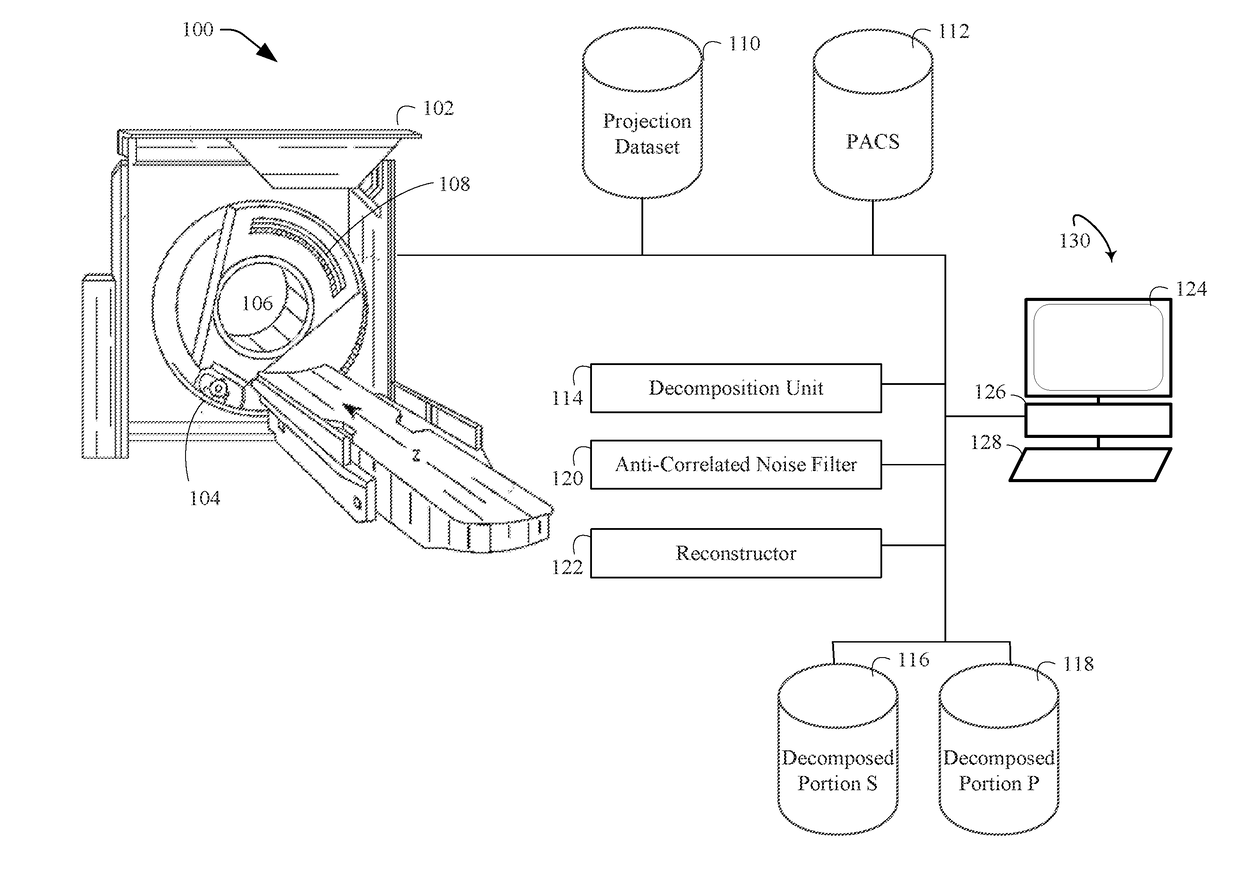
[0020]Initially referring to FIG. 1, an imaging system 100 includes an imaging scanner, such as a computed tomography (CT) scanner 102. The scanner is configured to generate projection data and / or images which decompose into anti-correlated portions. The scanner 102 includes one or more radiation sources 104, such as an x-ray tube, which emits radiation that traverses an examination region 106. In one instance, a mean or peak emission voltage of the radiation source 104 is switched between an emission voltage of two or more emission voltages (e.g., 80 and 140 kVp, 100 and 120 kVp, etc.). In another variation, the radiation source 104 includes a single broad spectrum x-ray tube.

[0021]A detector array 108 opposite the radiation source 104 detects the emitted radiation that traverses the examination region 106 and generates projection data 110 indicative of the object or subject in the examination region 106. Where the radiation source voltage is switched between at least two emission ...


PUM


Abstract

An imaging system (100) includes an anti-correlated noise filter (120), which jointly filters noise from a first portion (116) and a second portion (118), and the first portion (116) and the second portion (118) include anti-correlated noise.

Description

FIELD OF THE INVENTION[0001]The following generally relates to filtering image data and finds particular application to spectral computed tomography (CT), but is also amenable to other imaging processing systems.BACKGROUND OF THE INVENTION[0002]A computed tomography (CT) scanner includes an x-ray tube that emits radiation. The emitted radiation traverses an examination region with a subject or object located within and is detected by a detector array opposite from the x-ray tube. The detector array detects the radiation traversing the examination region and the subject located therein and generates projection data, e.g., raw detector data or projection images. A reconstructor processes the projection data and reconstructs a volumetric image of the subject or object.[0003]A spectral CT scanner includes at least one x-ray tube that emits a high energy spectrum and a low energy spectrum of x-rays, which elicit different structural and spectral characteristics of the subject or object i...

Claims


Application Information

Patent Timeline
Patent Type & Authority Applications(United States)
IPC IPC(8): G06T11/00
CPCG06T11/005G06T11/008G06T2211/408
Inventor BROWN, KEVIN MARTINGOSHEN, LIRANGRINGAUZ, ASHERZABIC, STANISLAV
Owner KONINKLJIJKE PHILIPS NV
Learn More