Reusable surgical instrument for minimally invasive procedures

Active Publication Date: 2018-01-04
DISTALMOTION
16 Cites 22 Cited by

AI-Extracted Technical Summary

Problems solved by technology

This results in a unique combination of safety ...

Benefits of technology

[0009]Theses aims and other advantages are achieved by a new articulated and reusable surgical instrument in the form of, for example, a dissector, scissor or grasper. The instrument comprises an articulated end-effector, placed at the distal extremity of an instrument shaft, which comprises an internal structural element and an external tube. The shaft defines the longitudinal axis of the instrument and is able to move according to the mobility constraints imposed by a body incision, which includes a rotational movement about its own axis. This rotation also causes the rotation of the end-effector, mounted on the distal extremity of the shaft. Thus, the instrument shaft has the triple function of (1) positioning the end-effector within the interior of the patient's body, (2) allowing the passage of the different transmission elements that are able to actuate the different distal end-effector articulations and (3) avoiding the passage of air through the instrument, in order to maintain the inflation of the body cavity where the i...

Abstract

Disclosed is a reusable surgical instrument (1) with an articulated end-effector (3), such as a dissector, scissor or grasper, to enhance a surgeon's performance during various surgical procedures. The longitudinal axis of the instrument is defined by a shaft (2), comprising an internal structural element (2″) covered by an external tube (2′), which may be inserted through a surgical incision into the body of a patient, optionally through a trocar. The articulated end-effector (3) is mounted on the distal extremity of the shaft's internal structural element and comprises a plurality of links interconnected by a plurality of joints, whose movements are remotely actuated by the surgeon's hands. This remote actuation is accomplished via mechanical transmission (5, 6, 7), mainly composed of flexible elements, which are able to deliver motion from a set of actuation elements, placed at a proximal extremity of the shaft (2), to the instrument's articulated end-effector (3). The external tube (2′) can be easily and individually detached from the shaft (2) after each procedure, so that the instrument (1) can be more effectively cleaned and sterilized.

Application Domain

Technology Topic

Image

  • Reusable surgical instrument for minimally invasive procedures
  • Reusable surgical instrument for minimally invasive procedures
  • Reusable surgical instrument for minimally invasive procedures

Examples

  • Experimental program(1)

Example

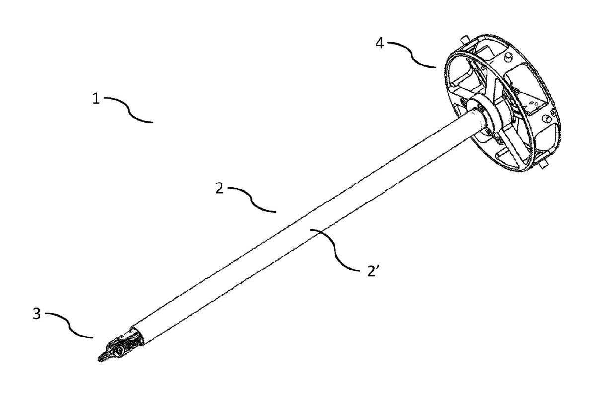
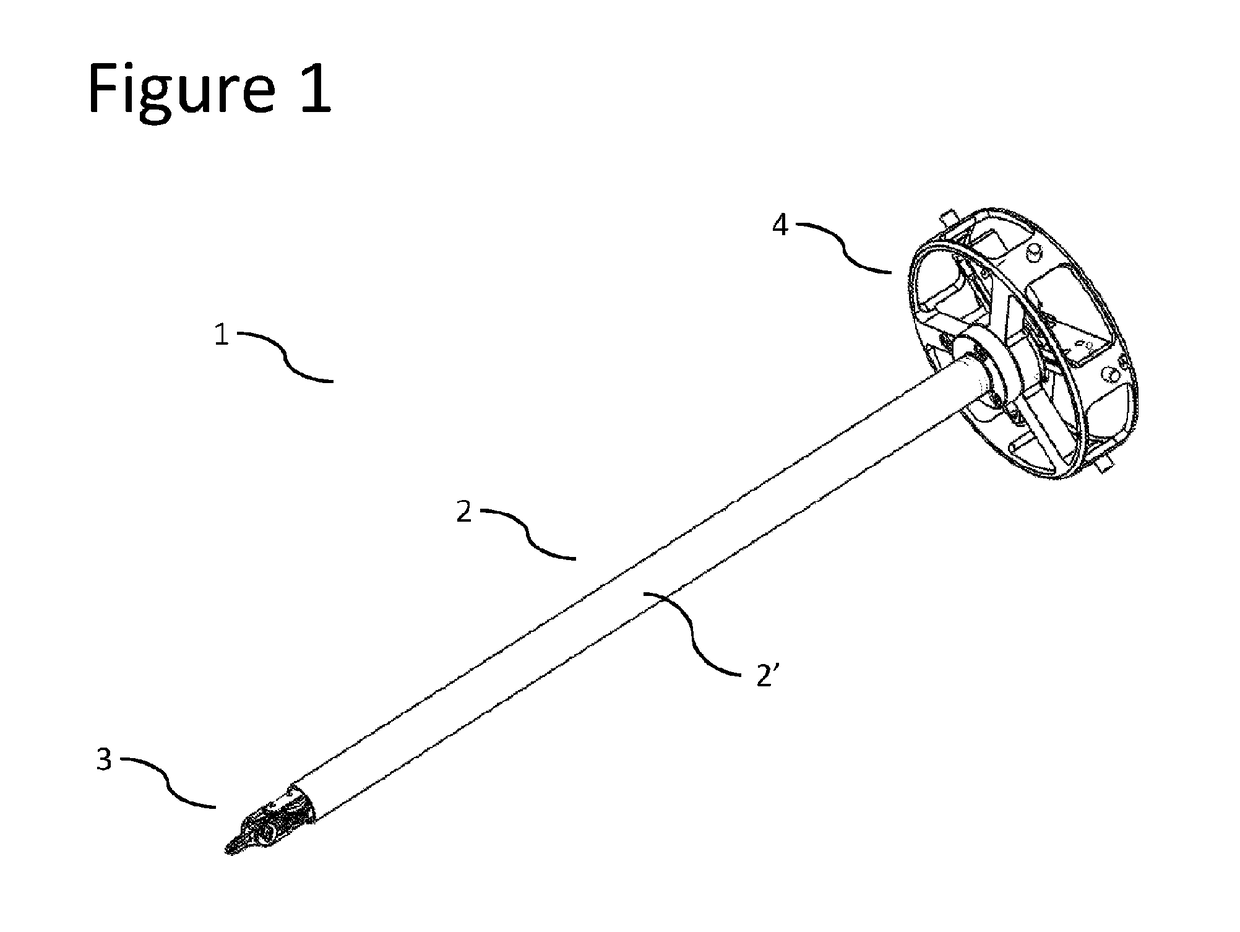
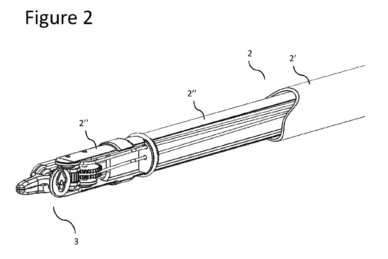
[0028]A reusable surgical instrument 1 for minimally invasive surgical procedures, with a detachable external tube 2′, constructed in accordance with an embodiment of the present invention, is described herein, and is seen generally in FIG. 1. This instrument 1 includes a main shaft 2, a distal articulated end-effector 3 and a proximal hub 4. Referring to FIG. 2, the shaft 2 is composed of two different elements: an internal structural element 2″ and an external tube 2′. The internal structural element 2″ provides a stable positioning to the end-effector 3 and to allow the passage of the different mechanical elements 5, 6, 7 that are able to deliver motion to the different end-effector links 8, 9, 10 from the proximal hub 4 at the proximal extremity of the instrument (FIGS. 3 and 4). The external tube 2′ protects the internal elements on the shaft 2 when passing through the incision and avoids the passage of air through the instrument 1, in order to maintain the inflation of the body cavity where the instrument 1 is operating.
[0029]Referring still to FIG. 4, the end-effector 3 is connected to the internal structural element 2″ by a proximal joint, which allows the rotation of the proximal end-effector link 8 about the proximal axis 11 in such a manner that the orientation of the proximal end-effector link 8 with respect to the main shaft axis 12 can be changed. The distal end-effector links 9, 10 are rotatably connected to the proximal end-effector link 8 by two distal joints, having coincident axes of rotation, which are represented by the distal axis 13. This distal axis 13 is substantially perpendicular and non-intersecting with the proximal axis 11 and substantially intersects the main shaft axis 12. FIGS. 5 to 9 show the surgical instrument 1 with different angular displacements at the end-effector joints. FIGS. 10 to 12 show the connection between the transmission element 5, 6, 7 and the end-effector links 8, 9, 10.
[0030]With reference to FIGS. 13 and 14, the movement is transmitted to each one of the three distal articulations of the instrument 1 by a rotating element 14, 15, 16, which is able to rotate about an axis 17 and is connected to a transmission element 5, 6, 7. As a result, when the rotating element 14, 15, 16 rotates a certain angle θ1, θ2, θ3 about the axis 17, a rotation α1, α2, α3 is transmitted to the respective end-effector member 8, 9, 10.
[0031]The external tube 2′ can be easily and individually detached and attached to the instrument 1 after each procedure. Referring to FIG. 15, the internal structural element 2″ is fixed directly to the proximal hub 4 and the external tube 2′ can be connected and disconnected from the internal structural element 2″ at the threaded surfaces 18a and 18b. Therefore, with this architecture, the external tube 2′ can be removed from the instrument 1, without the need to disassemble other parts of the system, like the articulated end-effector 3 or the mechanical transmission elements 5, 6, 7, which remain completely operational from a mechanical perspective without the external tube 2′. This feature facilitates the effective cleaning and sterilization of the instrument 1, which can easily be performed by the hospital staff.
[0032]Towards a more distal region of the instrument shaft 2, the external tube 2′ is in contact with a sealing element 19, which fills the gap between the internal surface of the external tube 2′ and the two transversal elements 20a, 20b that are mounted on the internal structural element 2″. These two transversal elements 20a, 20b have small channels 21a, 21b, 21c, 21d, 21e, 21f through which the transmission elements 5, 6, 7 can pass, guaranteeing the air-tightness of the instrument 1.
[0033]In some embodiments of the present invention, the mechanical transmission elements 5, 6, 7 may comprise ropes, whose tension can be released after each procedure, so that the cleaning and sterilization procedures become easier. By releasing the tension on the ropes, the blood and tissue infiltrated amongst the strands of the ropes can be more easily removed. In addition, areas of contact between the ropes and other mechanical elements (like pulleys, end-effector links 8, 9, 10 or rotating elements 14, 15, 16) can be more easily accessed.
[0034]While this invention has been shown and described with reference to particular embodiments thereof, it will be understood by those skilled in the art that various changes in form and details may be made therein without departing from the spirit and scope of the invention as defined by the appended claims. For instance, the external tube 2′ can be made out of different parts and can be attached to the proximal hub 4. In another embodiment, the internal structural element 2″ can also be composed of different parts and can assume different geometries with diverse cross sections, namely tubular (with openings) or U-shaped.
[0035]It will also be easily understood by one of skill in the art that the invention can easily be deployed in the context of other micro-manipulation tasks where complex instruments are used, but regular cleaning and/or sterilization of internal elements of an instrument shaft is desirable. Solely by way of example, micro-manipulation tasks are performed in contaminated environments, wherein thorough cleaning of instrument elements is required after each use. In this context, a detachable outer shaft allowing access to internal elements may be desirable.

PUM

no PUM

Description & Claims & Application Information

We can also present the details of the Description, Claims and Application information to help users get a comprehensive understanding of the technical details of the patent, such as background art, summary of invention, brief description of drawings, description of embodiments, and other original content. On the other hand, users can also determine the specific scope of protection of the technology through the list of claims; as well as understand the changes in the life cycle of the technology with the presentation of the patent timeline. Login to view more.

Similar technology patents

Classification and recommendation of technical efficacy words

Why Eureka
Try Eureka