Handlebar accessory mount

a technology for accessories and handles, applied in the direction of other supporting devices, cycle equipment, cycle containers, etc., can solve the problems of relative high cost, lack of security, and vulnerability to breakage, and achieve the effect of increasing the force needed

Active Publication Date: 2018-01-04
ALLEN JEFFREY M
View PDF12 Cites 17 Cited by
  • Summary
  • Abstract
  • Description
  • Claims
  • Application Information

AI Technical Summary

Benefits of technology

[0008]In the preferred embodiment of the invention, the dowel is inserted into openings in flanges extending from the camming lever, the flanges each having a overcenter camming surface that engages a cam-engaging surface of the bulkhead on two sides of the stud-receiving central opening in the first main body section, such that pivoting of the camming lever about the dowel in a first direction causes the dowel holding section of the camming level to move in an axial direction of the threaded stud, causing the second main body section and the second clamping jaw to move towards the first clamping jaw and thereby grip the accessory. The camming surface of the camming lever, and / or the cam-engaging surface of the bulkhead, preferably is shaped such that continued turning after a maximum clamping force has been achieved will provides an overcenter latching effect that prevents release of the camming lever to secure the clamping jaws in the gripping position. Release of the accessory can be achieved by pivoting the camming lever in the opposite direction past the point of maximum clamping force to cause the respective clamping jaws on the first and second main body sections to move apart from each other.
[0009]The spring bias in a direction opposite the clamping direction enables continued movement of the camming lever to and past the overcenter position and also exerts a force that resists pivoting of the camming lever in a release direction to thereby implement the overcenter latching effect after the clamping jaws have engaged the accessory and can no longer be moved towards each other. In addition, unintentional release of the accessory may be further positively prevented by optional detents or protrusions extending from the cam-engaging surface of the first main body section, in order to increase the force necessary to pivot the camming lever in the release direction. Adjustment of the gripping mechanism to fit different accessories is accomplished by turning the threaded stud to cause axial movement of the threaded stud relative to a fastening member that has been inserted into the corresponding slot in the second main body section to adjust the maximum initial separation between the first and second main body sections and therefore the initial spacing of the first and second clamping jaws.
[0010]Additional features of the gripping mechanism include resilient grips made of a material such as rubber and adhered to each of the clamping jaws. The resilient grips provide a tolerance in the clamping operation that ensures a tight grip without damaging the accessory.

Problems solved by technology

Disadvantages of the conventional mounting arrangements include, in the case of ratchet and pawl arrangements, complexity and relatively high cost, as well as vulnerability to breakage.
Disadvantages of adhesive-based or quick-release arrangements, lack of security in that the holder may become disengaged from the handlebar mount due to vibration or sudden movement of the vehicle.

Method used


Image

  • Handlebar accessory mount
  • Handlebar accessory mount
  • Handlebar accessory mount

Examples


Embodiment Construction

[0032]Throughout the following description and drawings, like reference numbers / characters refer to like elements. It should be understood that, although specific exemplary embodiments are discussed herein there is no intent to limit the scope of present invention to such embodiments. To the contrary, it should be understood that the exemplary embodiments discussed herein are for illustrative purposes, and that modified and alternative embodiments may be implemented without departing from the scope of the present invention.

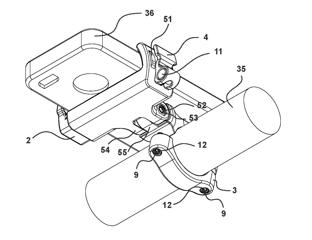
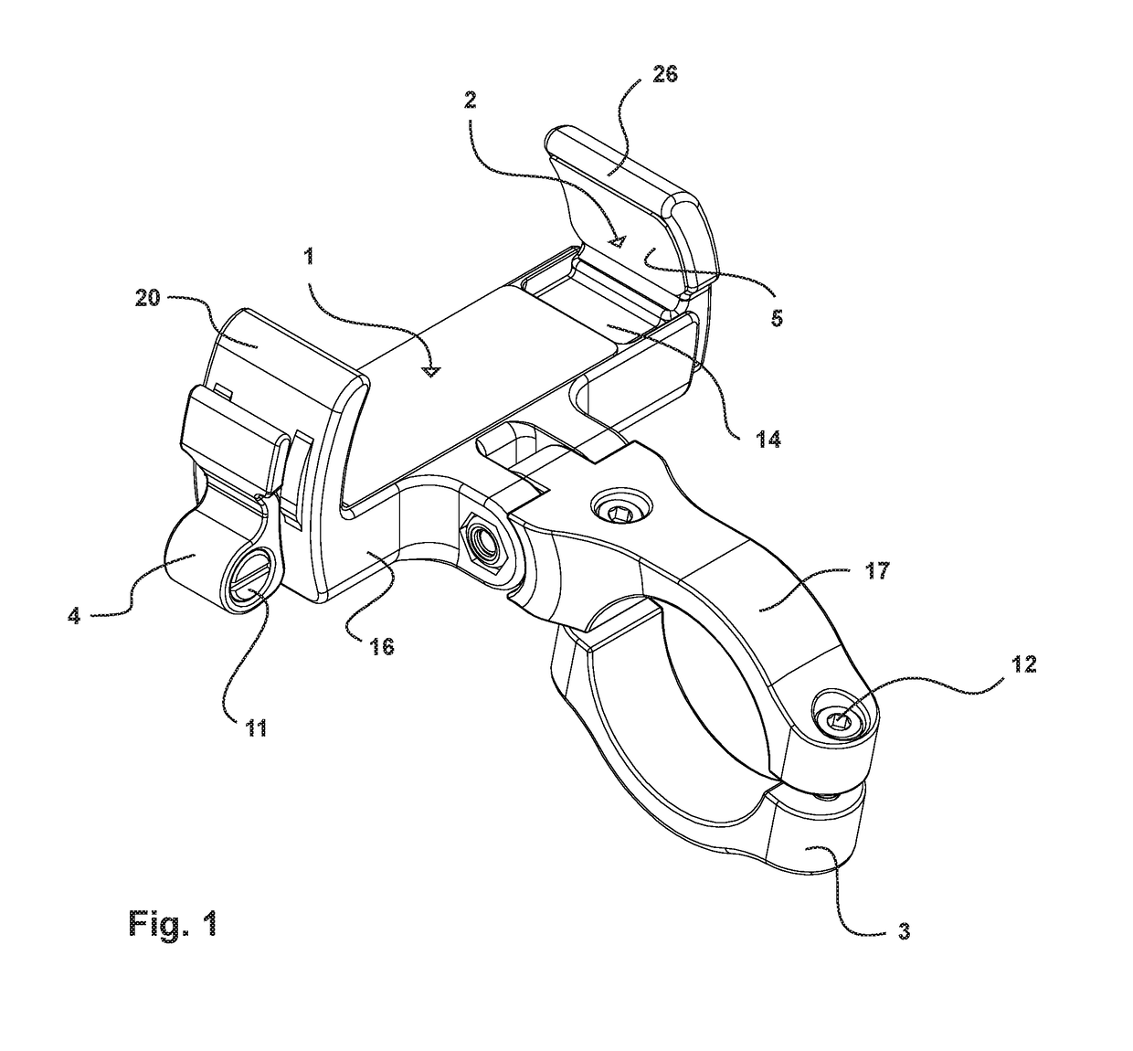
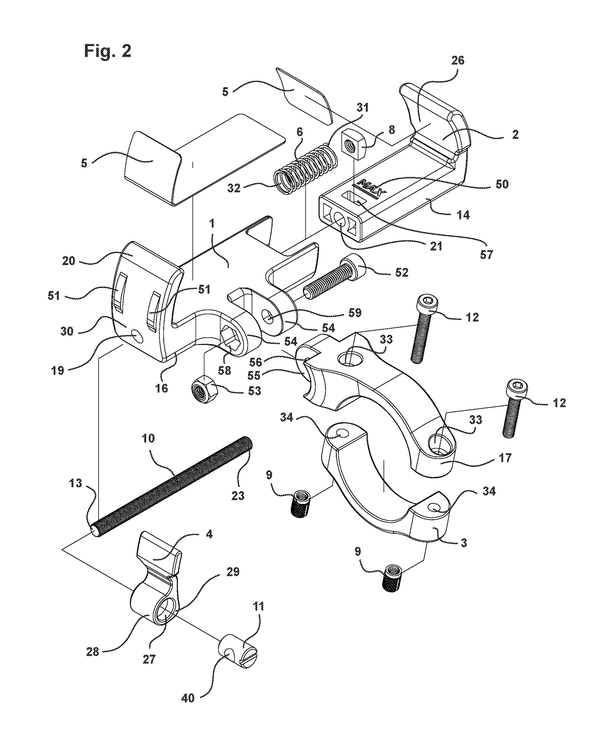
[0033]As shown in FIGS. 1-19, a gripping mechanism according to a preferred embodiment of the invention includes a first main body section 1 and a second main body section 2, a cam lever 4, a threaded stud 10, and a dowel 11 secured to a first end 13 of the threaded stud 10 by a fastener such as a hex socket head cap screw or with the use of adhesive in opening 40. The second main body section 2, best shown in FIGS. 16 and 17, includes a slider 14 arranged to be s...


PUM


Abstract

A cam lever operated accessory gripping mechanism the gripping mechanism includes a cam lever, a threaded stud, a dowel fixed to a first end of the threaded stud, first and second relatively movable main body sections, the first of the main body sections including a handlebar bracket extension, a first clamping jaw for engaging a first side of the accessory, and an opening shaped to slidably receive the second main body section, and the second main body section including a bore and a slot for receiving a fastening member into which the threaded stud is threaded, and a second clamping jaw for engaging a second side of the accessory. The dowel is rotatably mounted in the camming lever, which has at least one overcenter camming surface that engages a cam-engaging surface of the first main body section, such that pivoting of the camming lever about the dowel in a first direction causes the dowel holding section of the camming level to move in an axial direction of the threaded stud, pulling the second main body section against a biasing force provided by a biasing spring extending between the first and second main body sections, in a direction that causes the second clamping jaw to move towards the first clamping jaw and thereby grip the accessory. Adjustment of the gripping mechanism to fit different accessories is accomplished by turning the threaded stud to cause axial movement of the follower insert and corresponding movement of the second main body section is a desired direction, to adjust the initial spacing of the first and second clamping jaws.

Description

BACKGROUND OF THE INVENTION1. Field of the Invention[0001]The invention relates to a handlebar accessory mount, and in particular to a device for releasably mounting an accessory to a handlebar. The accessory may be, by way of example and not limitation, a smartphone.2. Description of Related Art[0002]Arrangements for releasably mounting smartphones and other portable electronic devices, such as trip computers and GPS devices, to the handlebar of a vehicle or apparatus, are currently commercially available. Vehicles with handlebars include bicycles, motorcycles, all-terrain vehicles, all-terrain vehicles, and strollers. Other apparatus that may include a handlebar include treadmills, stationary bicycles, and other exercise machines. By providing a temporary mount for the portable electronic device on the handlebar, the user is able to utilize features of the portable electronic device, such as audio or audiovisual entertainment, communications, and navigation, while leaving the user...

Claims


Application Information

Patent Timeline
Patent Type & Authority Applications(United States)
IPC IPC(8): B62J9/00
CPCB62J9/003B62J50/225B62J11/00B62J9/21
Inventor ALLEN, JEFFREY M.
Owner ALLEN JEFFREY M
Why Eureka
Try Eureka