
Stator Core and Motor Using the Same

Active Publication Date: 2018-01-04
LG INNOTEK CO LTD
View PDF15 Cites 5 Cited by
  • Summary
  • Abstract
  • Description
  • Claims
  • Application Information

AI Technical Summary

Benefits of technology

The patent text describes a new design for a magnet wire that eliminates the need for a separate wire-fixing component during wiring operations. This design also prevents damage to the wire's insulated film caused by external forces, such as vibration. Additionally, the patent text discusses how this design prevents short-circuiting between winding portions of the wire, which can be achieved without the need for a separate component. This improvement in processibility eliminates the need for separate after-treatment processes to prevent damage to the wire's insulated film.

Problems solved by technology

Particularly, the insulator has a structure where a coil is wound, and when a wire, generally called a magnet wire, is wound on the insulator, an outermost coil is not fixed to generate damage or cut problem on an insulated film of the magnet wire due to trembling phenomenon caused by outside vibration.

Method used


Image

  • Stator Core and Motor Using the Same
  • Stator Core and Motor Using the Same
  • Stator Core and Motor Using the Same

Examples


Embodiment Construction

Technical Subject

[0004]The teachings in accordance with exemplary and non-limiting embodiments of this disclosure are to provide solve the abovementioned problem by providing a protruding pattern part fixing a distal end of a magnet wire to remove a wire-fixing operation using a separate member during wiring operation, whereby a processibility can be improved and a stator core preventing damage to insulated film of the magnet wire caused by outside force such as vibration can be provided.

Technical Solution

[0005]In one general aspect of the present invention, there is provided a stator coil, the stator coil comprising:

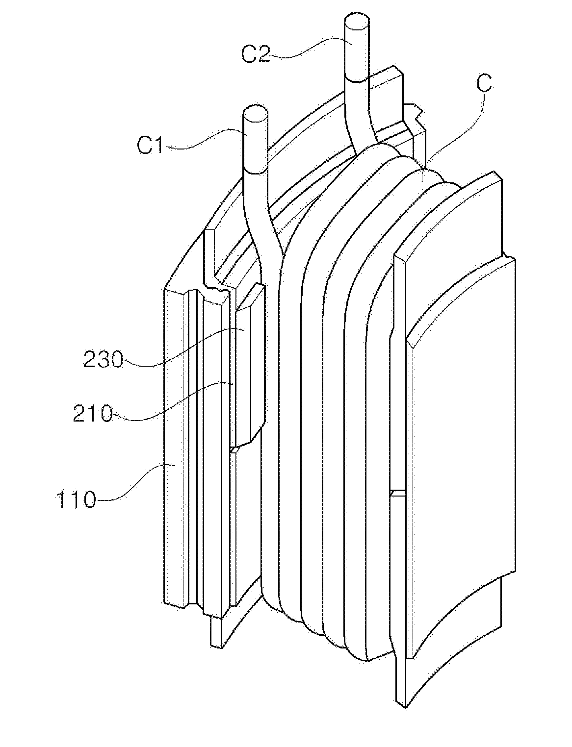
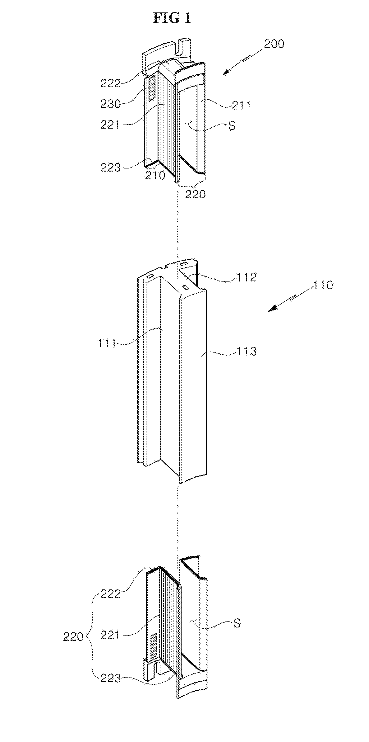
[0006]a unit stator core provided with a tooth protruded from a head part;

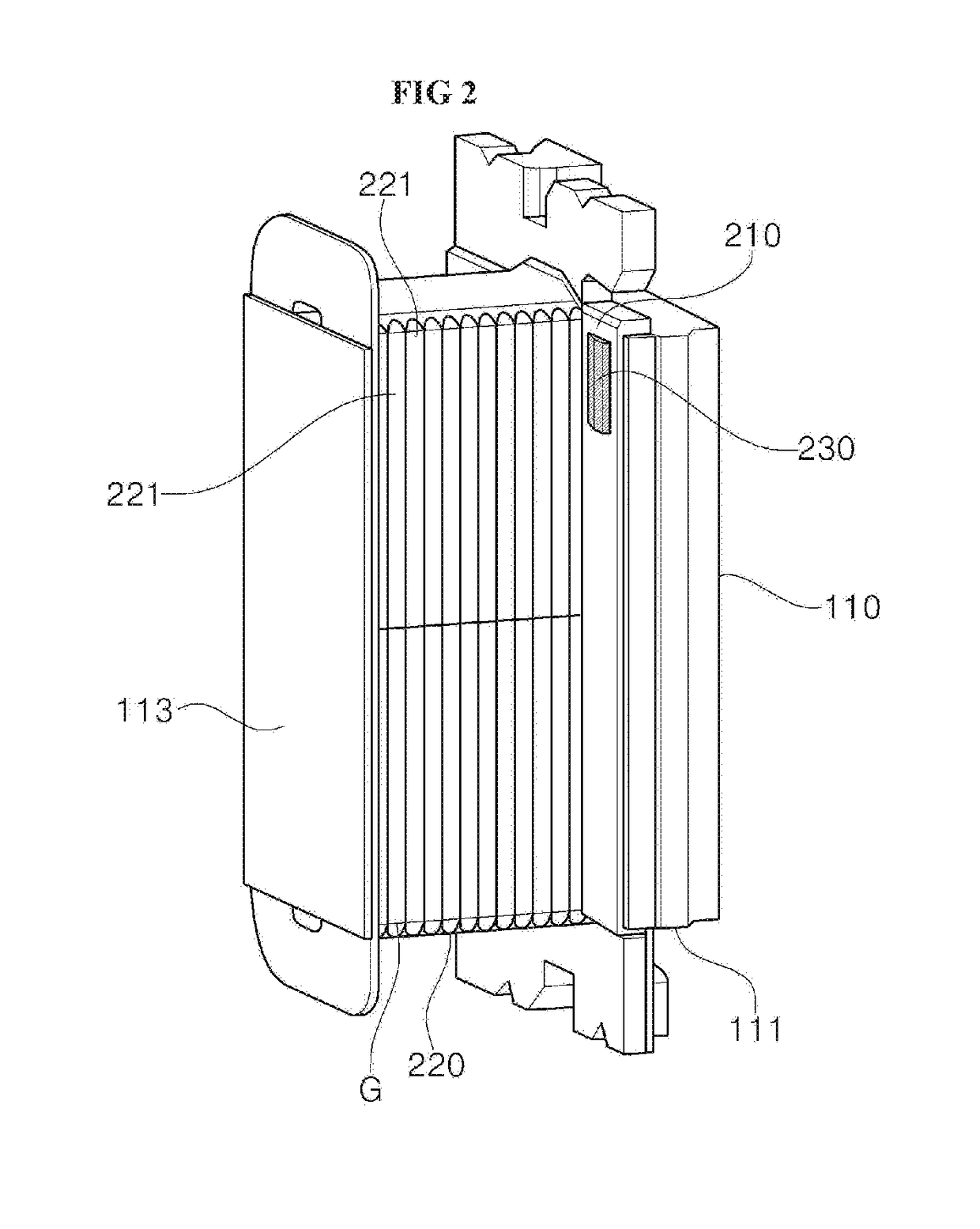
[0007]an insulation member coupled to the unit stator core and wound with a coil; and

[0008]a coil-fixing protrusion pattern part provided on a surface of the insulation member.

[0009]Preferably, but not necessarily, the insulation member may include a body part wound with a coil and provided with a...


PUM


Abstract

The present invention relates to a stator core for improving the fixing properties of a magnet wire, and a motor in which the same is applied. Provided is a stator core which comprises a protrusion pattern part for fixing the distal end portion of a magnet wire, and thus eliminates a process of fixing the wire using a separate member during a wiring process, thereby improving processability and preventing an insulating film of the magnet wire from being damaged by an external force such as vibration.

Description

TECHNICAL FIELD[0001]The teachings in accordance with exemplary and non-limiting embodiments of this disclosure relate generally to a stator core improved in fixability of magnet wire and a motor using the same.BACKGROUND ART[0002]In general, a motor is mainly composed of a stator and a rotor, and the stator is wound with a coil, and the rotor is coupled with a magnet to cause rotating due to mutual electromagnetic action with the magnet. The stator is formed with a unit core and a coil, and recently, a plurality of divided coils is connected in a ring shape to be used as a stator. An insulator (hereinafter referred to simply as“insulator”) is inserted to insulation between the core and the coil.[0003]Particularly, the insulator has a structure where a coil is wound, and when a wire, generally called a magnet wire, is wound on the insulator, an outermost coil is not fixed to generate damage or cut problem on an insulated film of the magnet wire due to trembling phenomenon caused by ...

Claims


Application Information

Patent Timeline
IPC IPC(8): H02K1/16H02K1/27
CPCH02K1/16H02K1/272H02K1/146H02K3/522H02K3/345H02K1/12H02K3/46H02K2203/12
Inventor KONG, BONG BAE
Owner LG INNOTEK CO LTD
Learn More