Vehicular display control apparatus and vehicular display control method

Active Publication Date: 2018-01-11
DENSO CORP
View PDF0 Cites 6 Cited by
  • Summary
  • Abstract
  • Description
  • Claims
  • Application Information

AI Technical Summary

Benefits of technology

[0064]Examples of advantageous effects offered in the first embodiment presented herein are now described.
[0065]According to the first embodiment, the speed display 56v displayed by the HUD 50 of the subject vehicle 2 to indicate the traveling speed is switched to the emphasized display 56e in a particular state. The particular state herein is a state that a deviation is predicted between the actual traveling speed and the sensible speed of the driver, and that the speed difference between the speed limit of the traveling road and the actual traveling speed becomes the switching determination value or larger. In this case, the driver viewing the emphasized display 56e in the foregoing state is urged to perform safe driving of the subject vehicle 2, and it may be possible to control the traveling speed by driver intension. With this, it may be possible to decrease an uncomfortable feeling of the driver caused by safe traveling assistance.
[0066]According to the first embodiment, the speed difference between the speed limit and the traveling speed is determined before the traveling speed is forcedly reduced to the speed limit or lower by the integration control ECU configured by the vehicle control ECU 42 of the subject vehicle 2. In this case, the driver viewing the emphasized display 56e is urged to perform safe traveling when the speed difference becomes the switching determination value or larger prior to forced speed reduction in a state of prediction of a deviation between the sensible speed and the traveling speed. Accordingly, it may be possible to decrease an uncomfortable feeling caused by forced speed reduction.
[0067]According to the first embodiment, the driver viewing the emphasized display 56e formed by expanding the speed display 56v intuitively can recognize a state in need of control of the traveling speed. In particular in the first embodiment, the emphasized display 56e formed by expanding the speed display 56v toward the driver seat 20 is easily viewed by the driver sitting on the driver seat 20. In this case, the state

Problems solved by technology

In this case, a driver may feel uncomfortable by th

Method used


Image

  • Vehicular display control apparatus and vehicular display control method
  • Vehicular display control apparatus and vehicular display control method
  • Vehicular display control apparatus and vehicular display control method

Examples


first embodiment

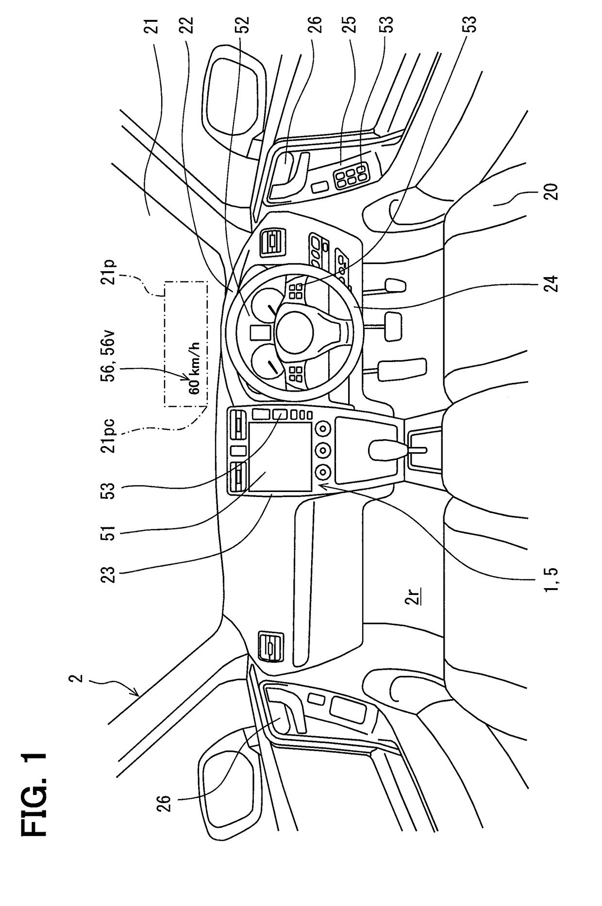
[0030]As illustrated in FIG. 1 and FIG. 2, a traveling assist system 1 according to a first embodiment to which the present disclosure has been applied is mounted on a subject vehicle 2. In the following description, a traveling speed of the subject vehicle 2 is referred to as a traveling speed, and a time and time zone of traveling of the subject vehicle 2 are referred to as a traveling time and a traveling time zone, respectively. In addition, a road on which the subject vehicle 2 travels is referred to as a traveling road, a position of the subject vehicle 2 on the traveling road is referred to as a traveling position, and a speed limit for the subject vehicle 2 on the traveling road is referred to as a speed limit.

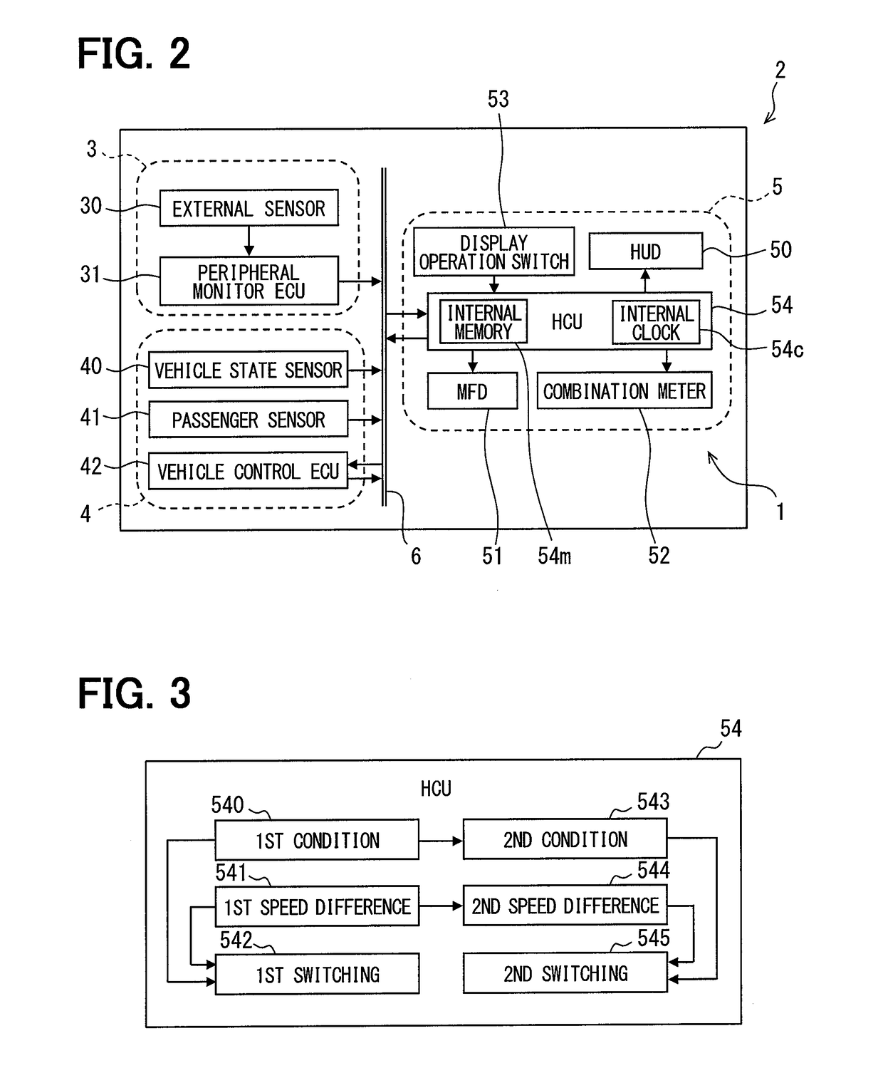
[0031]The traveling assist system 1 is configured by a peripheral monitoring system 3, a vehicle control system 4, and a display system 5. The systems 3, 4, and 5 of the traveling assist system 1 are connected to each other via an in-vehicle network 6 such as a local a...

second embodiment

[0076]A second embodiment of the present disclosure illustrated in FIGS. 10 and 11 is a modification of the first embodiment. As illustrated in FIG. 10, a speed display 2056v indicating a speed limit as well as a traveling speed is provided by an HUD 2050 functioning as a display unit in a display system 2005 of the second embodiment. The speed limit herein is displayed on an image 2056I indicating a speed limit sign, for example, at a position adjacent to the traveling speed displayed similarly to the first embodiment.

[0077]According to the second embodiment, the speed display 2056v displayed by the HUD 2050 as illustrated in FIG. 10 is switched to an emphasized display 2056e in FIG. 11 under control by the first switching control block 542 of the HCU 54. The emphasized display 2056e herein corresponds to an image 2056 whose display states of both the traveling speed and the speed limit are expanded into more emphasized and more noticeable display states than the display state of t...

third embodiment

[0080]A third embodiment of the present disclosure illustrated in FIGS. 12 and 13 is a modification of the first embodiment. As illustrated in FIG. 12, a display system 3005 according to the third embodiment is not equipped with the HCU 54. Accordingly, display ECUs 3050c, 3051c, and 3052c, each of which is mainly configured by a microcomputer, are included in display elements 3050, 3051, and 3052 of the display system 3005, respectively, and connected to the in-vehicle network 6 to which the display operation switches 53 are also connected. In the display system 3005 thus structured, the control function of the HCU 54 described in the first embodiment is split into partial functions performed by the display ECUs 3050c, 3051c, and 3052c of the respective display elements 3050, 3051, and 3052. For example, the navigation display control is executed at least by the display ECU 3051c of the MFD 3051. The speed display control is executed by each of the display ECU 3050c of the HUD 3050...


PUM


Abstract

A vehicular display control apparatus includes: a condition determination portion that determines whether a deviation prediction condition has been established, the deviation prediction condition being a condition based on which a deviation between a sensible speed for a driver and an actual traveling speed is predicted; a speed difference determination portion that determines whether a speed difference between the actual traveling speed and a speed limit is a switching determination value or larger, and whether a shortage of the traveling speed from the speed limit is the switching determination value or larger; and a switching control portion that switches a speed display indicating the traveling speed to an emphasized display in a case when the condition determination portion determines that the deviation prediction condition has been established, and also when the speed difference determination portion determines that the speed difference is the switching determination value or larger.

Description

CROSS REFERENCE TO RELATED APPLICATIONS[0001]The present application is based on Japanese Patent Application No. 2014-252261 filed on Dec. 12, 2014, the disclosures of which is incorporated herein by reference.TECHNICAL FIELD[0002]The present disclosure relates to a vehicular display control apparatus and a vehicular display control method, which control display of a display unit of a vehicle.BACKGROUND ART[0003]It has been known that a deviation may be produced between a sensible speed for a driver of a vehicle during traveling of the vehicle and an actual traveling speed of the vehicle. For example, a deviation between the traveling speed and the sensible speed may be easily produced when a traveling road of the vehicle switches to an ordinary road from a highway allowing a higher legal speed limit than that of the ordinary road.[0004]In order to secure safe traveling of the subject vehicle even under such a deviation, a technology disclosed in Patent Literature 1 forcedly reduces...

Claims


Application Information

Patent Timeline
IPC IPC(8): G08G1/0967B60K35/00
CPCG08G1/0967B60K35/00B60K2350/1076B60K2350/352B60K2350/965B60R21/00G08G1/09G08G1/16G08G1/09623B60K2370/1529B60K2370/191B60K2370/168B60K2370/167B60K2370/16B60K2370/52B60K2370/193B60K2370/1868
Inventor NONOYAMA, YUJI
Owner DENSO CORP
Why Eureka
Try Eureka