Laminated coil component and matching circuit
a technology of laminated coils and components, applied in the direction of impedence networks, transformers/inductance details, inductances, etc., can solve the problems of unnecessary coupling between deterioration of characteristics due to unnecessary coupling between adjacent components, and unnecessary coupling of coils and conductor layers, etc., to achieve high accuracy
- Summary
- Abstract
- Description
- Claims
- Application Information
AI Technical Summary
Benefits of technology
Problems solved by technology
Method used
Image
Examples
first preferred embodiment
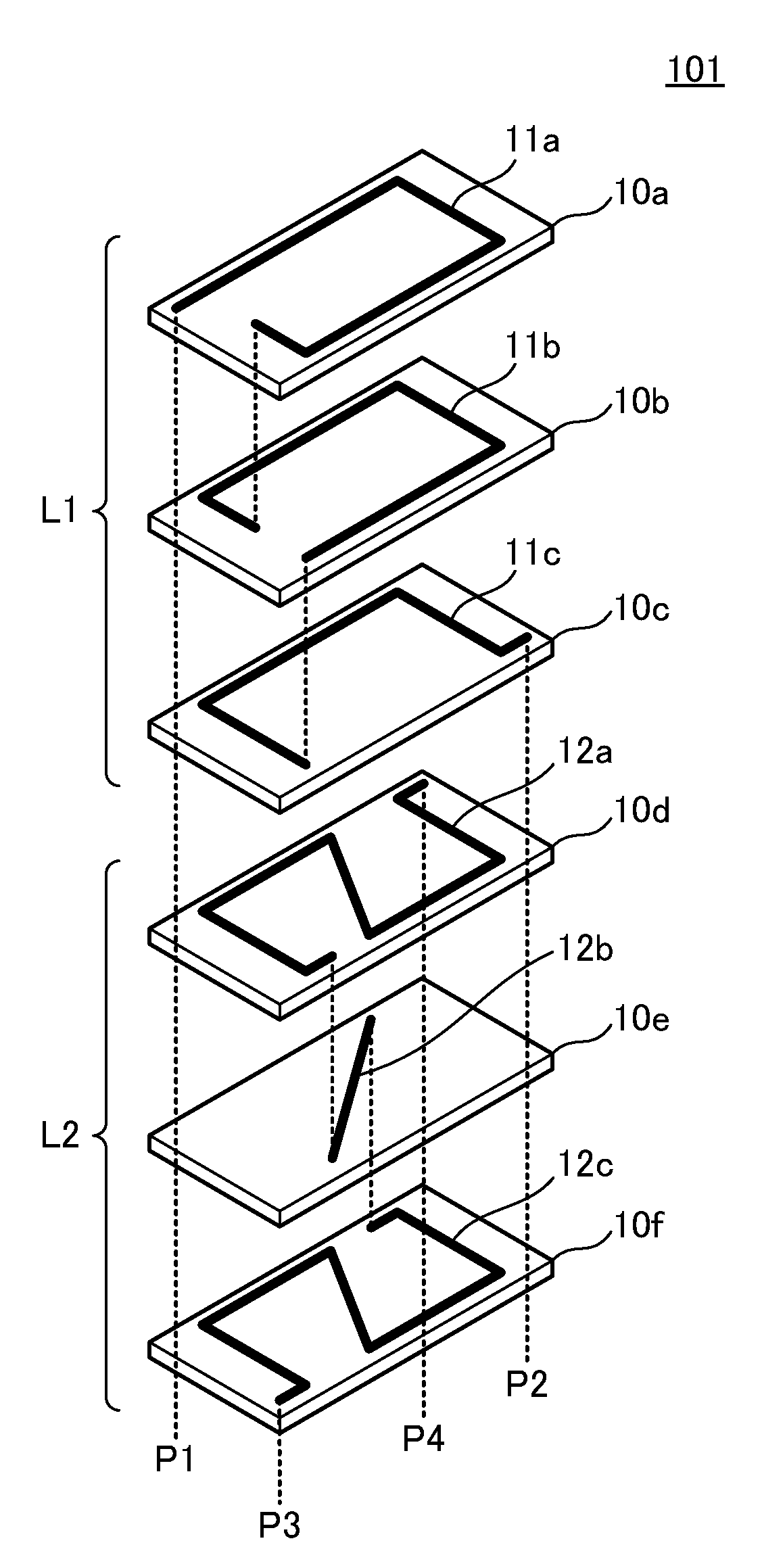
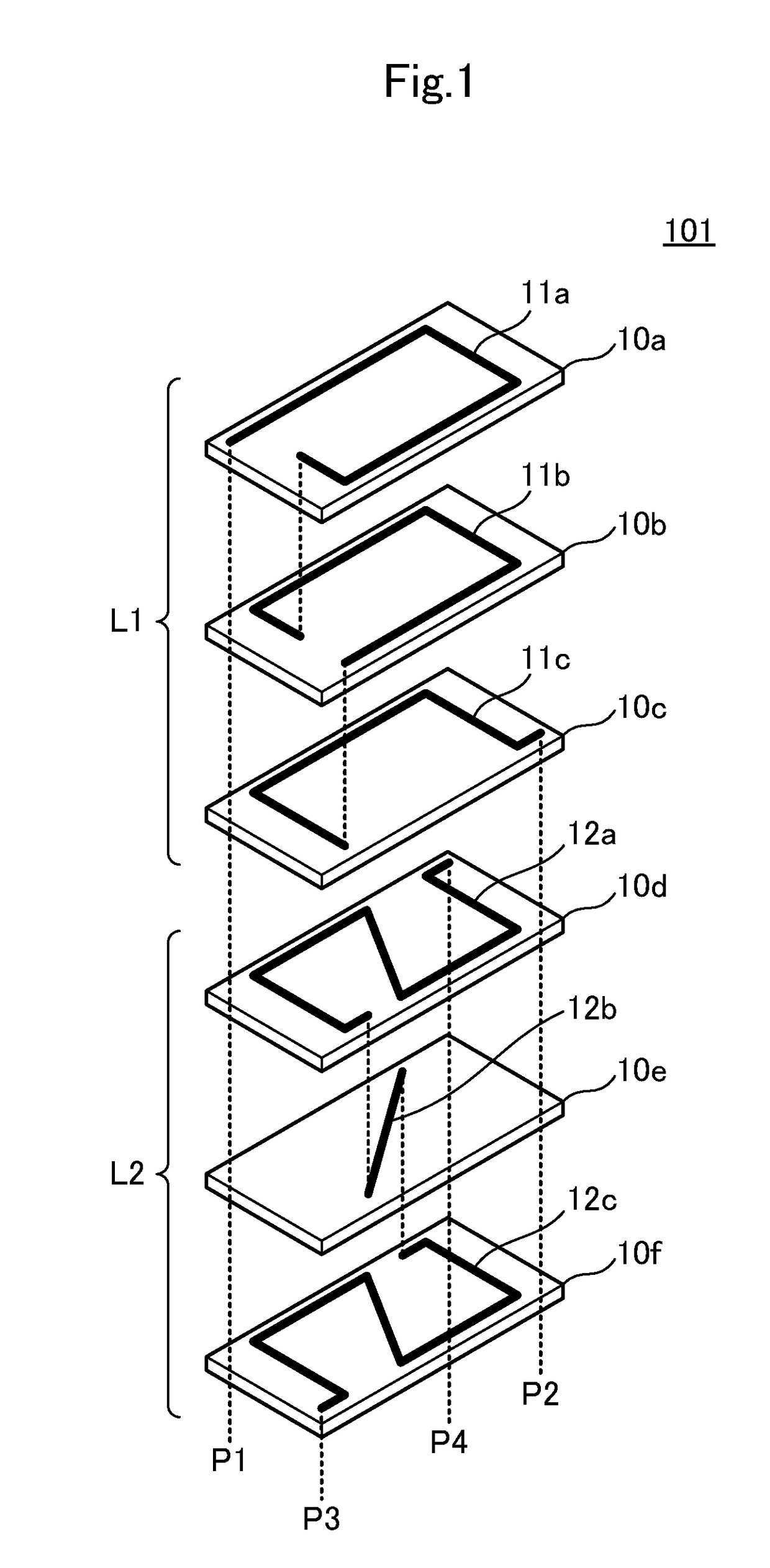
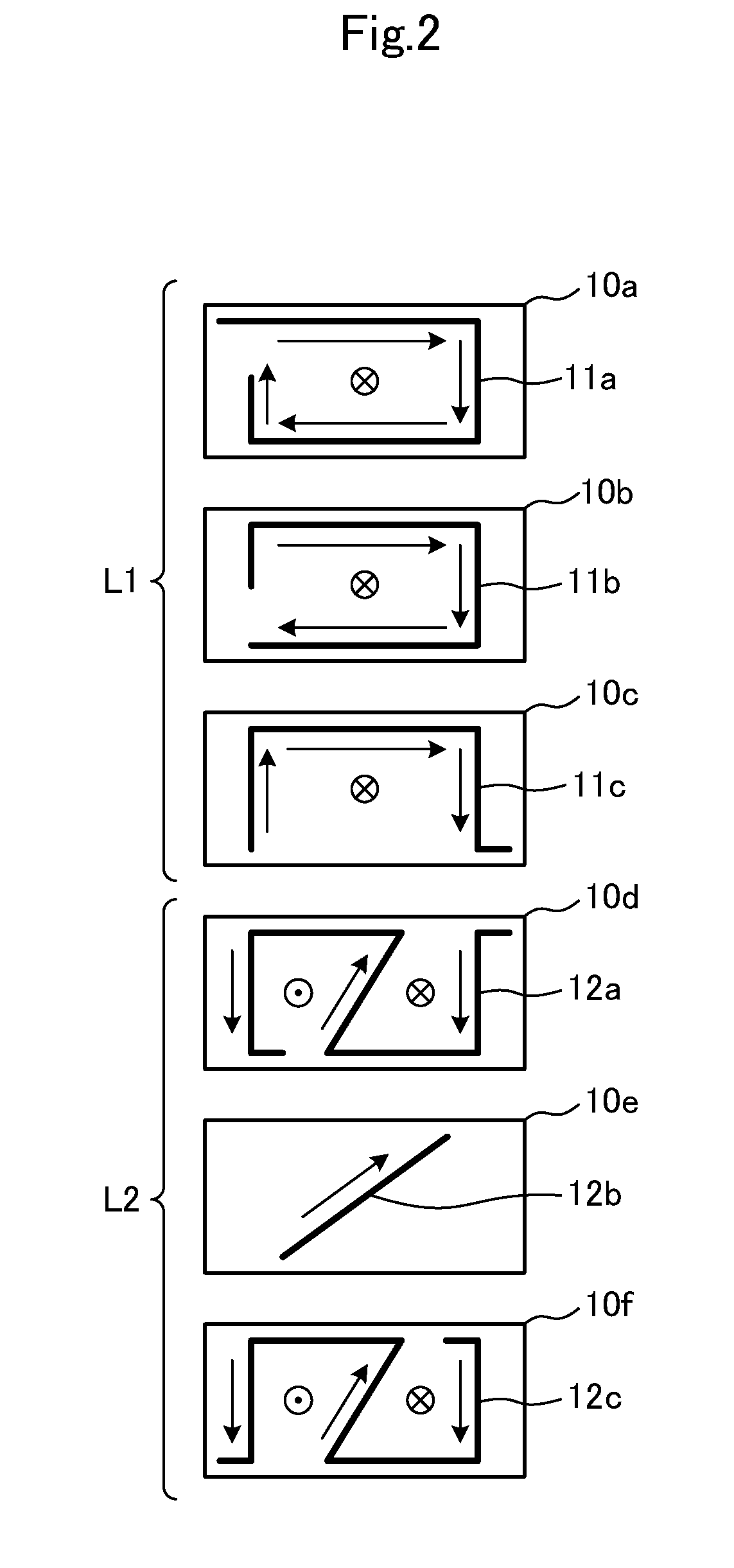
[0038]FIG. 1 is an exploded perspective view of a main portion of a laminated coil component 101 according to a first preferred embodiment of the present invention.
[0039]The laminated coil component 101 includes insulating layers 10a to 10f that are laminated on each other, each of the insulating layers 10a to 10f including at least one conductor pattern; and at least one coil defined by the conductor patterns. The conductor patterns include first coil conductor patterns 11a, 11b, and 11c, and second coil conductor patterns 12a, 12b, and 12c. In other words, the insulating layers 10a, 10b, and 10c include the first coil conductor patterns 11a, 11b, and 11c, respectively, and the insulating layers 10d, 10e, and 10f include the second coil conductor patterns 12a, 12b, and 12c, respectively. The respective conductor patterns are interlayer-connected to each other through via conductors (not shown) at predetermined positions. The laminated coil component includes an external terminal on...
second preferred embodiment
[0050]FIG. 6 is an exploded perspective view of a main portion of a matching circuit 201 according to a second preferred embodiment of the present invention. FIG. 7 is a plan view showing the respective insulating layers of the matching circuit 201.
[0051]The matching circuit 201 includes insulating layers 10a to 10l that are laminated on each other, each of the insulating layers 10a to 10l including at least one conductor pattern; and at least one coil defined by the conductor patterns. The conductor patterns include first coil conductor patterns 11a to 11d, and second coil conductor patterns 12a to 12c. The respective conductor patterns are interlayer-connected to each other through via conductors (not shown) at predetermined positions. The insulating layers 10a to 10d include first coil conductor patterns 11a to 11d. The insulating layers 10e to 10g include second coil conductor patterns 12a to 12c. The insulating layers 10h to 10j include capacitor electrodes 21 to 23. The insula...
third preferred embodiment
[0055]FIG. 9 is an exploded perspective view of a main portion of a matching circuit 202 according to a third preferred embodiment of the present invention. FIG. 10 is a plan view showing the respective insulating layers of the matching circuit 202. FIG. 11A is a view showing first coil conductor patterns 11a, 11b, 11c, and 11d of the matching circuit 202 that are overlapped, and FIG. 11B is a view showing second coil conductor patterns 12a, 12b, and 12c of the matching circuit 202 that are overlapped. FIG. 12 is a cross sectional view of a portion of layers including a coil conductor pattern of the matching circuit 202. Furthermore, FIG. 13 is a circuit diagram of the matching circuit 202.
[0056]The matching circuit 202 differs from the matching circuit 201 according to the second preferred embodiment of the present invention in that the second coil conductor patterns 12a, 12b, and 12c have different shapes. As shown in FIG. 9 and FIG. 10, a shape defined by the second coil conducto...
PUM
 Abstract
Description
Claims
Application Information
 - R&D
- Intellectual Property
- Life Sciences
- Materials
- Tech Scout
- Unparalleled Data Quality
- Higher Quality Content
- 60% Fewer Hallucinations
Browse by: Latest US Patents, China's latest patents, Technical Efficacy Thesaurus, Application Domain, Technology Topic, Popular Technical Reports.
© 2025 PatSnap. All rights reserved.Legal|Privacy policy|Modern Slavery Act Transparency Statement|Sitemap|About US| Contact US: help@patsnap.com


