Circuit module

a circuit module and circuit technology, applied in the field of circuit modules, can solve problems such as magnetic flux leakage around non-reciprocal circuit elements, and achieve the effect of significantly reducing the occurrence of magnetic coupling between non-reciprocal circuit elements and preventing them

Inactive Publication Date: 2013-11-12
MURATA MFG CO LTD
View PDF15 Cites 0 Cited by
  • Summary
  • Abstract
  • Description
  • Claims
  • Application Information

AI Technical Summary

Benefits of technology

[0007]Preferred embodiments of the present invention provide a circuit module in which a plurality of non-reciprocal circuit elements, each of which does not have a yoke, are mounted, and in which magnetic coupling between the non-reciprocal circuit elements is significantly reduced and prevented.
[0008]A circuit module according to a preferred embodiment of the present invention includes a circuit board; and a first non-reciprocal circuit element and a second non-reciprocal circuit element each of which is mounted on the circuit board, generates magnetic flux in a direction parallel or substantially parallel to a principal surface of the circuit board, and does not have a yoke to reduce leakage of magnetic flux to an outside. The first non-reciprocal circuit element and the second non-reciprocal circuit element are arranged to significantly reduce and prevent magnetic coupling therebetween.
[0009]A circuit module according to another preferred embodiment of the present invention includes a circuit board; a first non-reciprocal circuit element and a second non-reciprocal circuit element each of which is mounted on the circuit board, generates magnetic flux in a direction parallel or substantially parallel to a principal surface of the circuit board, does not have a yoke to reduce leakage of magnetic flux to an outside; and a magnetic material arranged to prevent magnetic flux from entering the first non-reciprocal circuit element and the second non-reciprocal circuit element. A first recess and a second recess in which the first non-reciprocal circuit element and the second non-reciprocal circuit element are provided, respectively, are provided in the circuit board. The magnetic material is provided on a side surface of the first recess which is located between the first non-reciprocal circuit element and the second non-reciprocal circuit element.
[0010]According to various preferred embodiments of the present invention, in a circuit module in which a plurality of non-reciprocal circuit elements, each of which does not have a yoke, are mounted, occurrence of magnetic coupling between the non-reciprocal circuit elements is significantly reduced and prevented.

Problems solved by technology

However, when the yoke is removed from the non-reciprocal circuit element, magnetic flux leaks around the non-reciprocal circuit element.

Method used


Image

  • Circuit module
  • Circuit module
  • Circuit module

Examples


Embodiment Construction

[0022]Hereinafter, a circuit module according to various preferred embodiments of the present invention will be described with reference to the drawings.

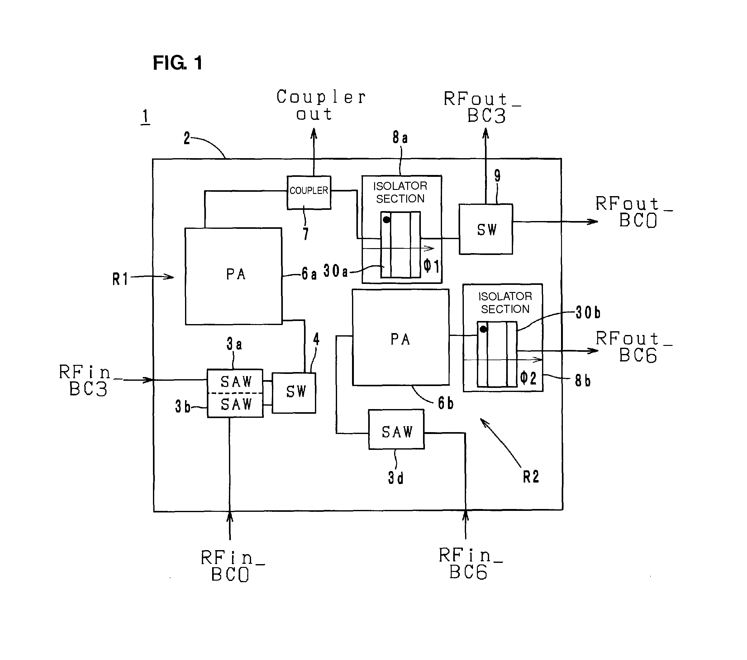
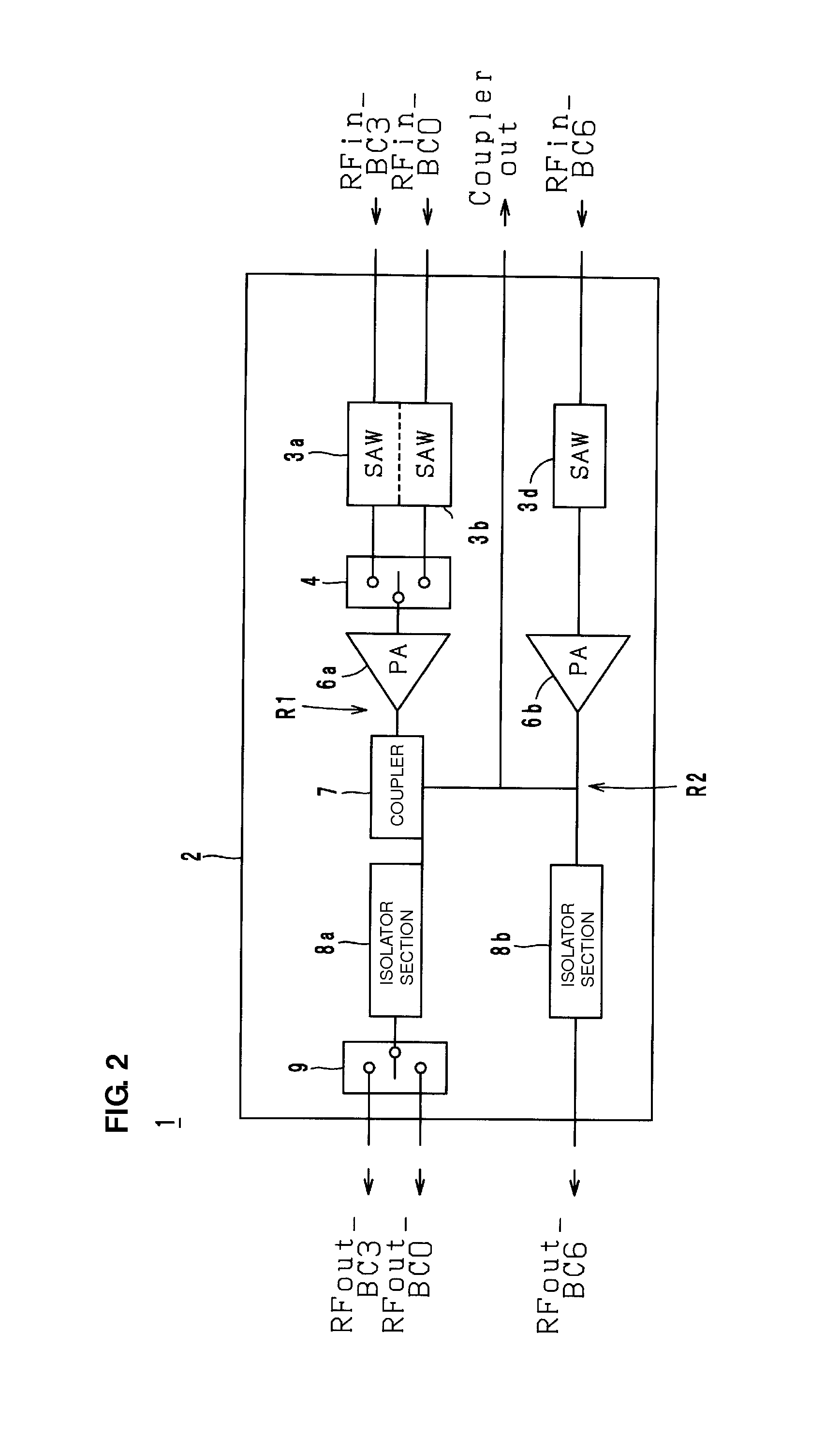
[0023]First, the configuration of the circuit module will be described with reference to the drawings. FIG. 1 is an arrangement diagram of electronic components mounted on a circuit module 1 according to a preferred embodiment of the present invention. FIG. 2 is a block diagram of the circuit module 1 in FIG. 1. In FIG. 1, only major electronic components are shown, and minor electronic components such as chip capacitors and chip inductors are omitted.

[0024]The circuit module 1 preferably constitutes a portion of a transmission circuit of a wireless communication apparatus such as a cellular phone, and amplifies and outputs multiple types of radio-frequency signals. The circuit module 1 includes a circuit board 2 and transmission paths R1 and R2. The circuit board 2 is a plate-shaped multilayer printed board on which and in which el...


PUM


Abstract

In a circuit module in which a plurality of non-reciprocal circuit elements, each of which does not have a yoke, are mounted, the occurrence of magnetic coupling between the non-reciprocal circuit elements is significantly reduced and prevented. Core isolators are not arranged such that, in a state in which the direction of magnetic flux and the direction of magnetic flux are the same, the core isolators are aligned in the direction of the magnetic flux. Specifically, the core isolators generate the magnetic flux from left to right. The core isolators are aligned so as to be inclined relative to the magnetic flux. Thus, extension of the magnetic flux through the core isolator in a state of being directed in the same direction as that of the magnetic flux is significantly reduced and prevented.

Description

BACKGROUND OF THE INVENTION[0001]1. Field of the Invention[0002]The present invention relates to a circuit module, and more specifically, relates to a circuit module in which a plurality of non-reciprocal circuit elements are provided.[0003]2. Description of the Related Art[0004]As an existing non-reciprocal circuit element, for example, a non-reciprocal circuit element described in Japanese Unexamined Patent Application Publication No. 2006-311455 is known. The non-reciprocal circuit element includes a ferrite having a pair of opposing principal surfaces, a plurality of center electrodes, permanent magnets having principal surfaces facing the principal surfaces of the ferrite, and a circuit board. The plurality of center electrodes are formed from a conductor film in a state of being insulated from the principal surfaces of the permanent magnets and intersecting each other, and are electrically connected via intermediate electrodes formed on end surfaces orthogonal to the principal...

Claims


Application Information

Patent Timeline
Patent Type & Authority Patents(United States)
IPC IPC(8): H01P1/387H01P1/36
CPCH01P1/387H01P1/36H05K1/0243H05K1/0233H05K2201/083
Inventor ISHIYAMA, YOSHIYUKITAKAHASHI, YASUHIROFURUTANI, KOJI
Owner MURATA MFG CO LTD
Why Eureka
Try Eureka