Ignition coil

a technology of ignition coil and coil body, which is applied in the direction of electric ignition installation, mechanical equipment, machines/engines, etc., can solve the problems of large expenditure, insufficient engine compartment space, and insufficient space above the cylinder bank

Active Publication Date: 2021-11-25
ROSENBERGER HOCHFREQUENZTECHNIK GMBH & CO KG
View PDF0 Cites 0 Cited by
  • Summary
  • Abstract
  • Description
  • Claims
  • Application Information

AI Technical Summary

Benefits of technology

[0083]FIG. 4B shows a three-dimensional illustration of an ignition coil with a second implementation for minimizing the electrical coupling of the HF voltage into the primary side of the ignition coil,
[

Problems solved by technology

The space in the engine compartment, in particular in the area above the cylinder bank, is typically not sufficient for this.
Spatial separation of the ignition coil and of the bandpass filter in two separate housings add

Method used


Image

  • Ignition coil
  • Ignition coil
  • Ignition coil

Examples


first embodiment

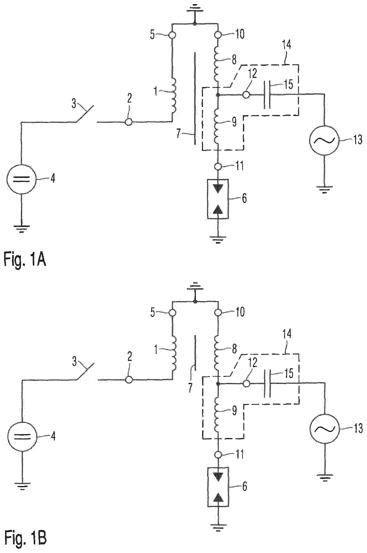
[0090]In the circuit diagram in FIG. 1A, an arrangement for integrating an ignition coil according to the present disclosure with a bandpass filter is illustrated:

[0091]The first coil 1 is connected at one end to the electrode of a DC voltage source 4, preferably a battery, via a DC voltage terminal 2 of the ignition coil, a switch 3. The other electrode of the DC voltage source 3 is connected to a ground potential. The further electrode of the first coil 1 is also connected to a ground potential via a ground terminal 5 of the ignition coil. In the phase before the ignition of the spark plug 6, which is connected to the ignition coil, the switch 3 is closed. A DC current, which is driven by the DC voltage of the DC voltage source 5, flows through the first coil 1 of the ignition coil.

[0092]In order to fire the spark plug 5, the switch 3 is opened, and therefore the flow of current through the first coil 1 is interrupted. This interruption of the flow of current induces a voltage pul...


PUM


Abstract

The present invention relates to an ignition coil for generating a high-voltage pulse with a superimposed high-frequency voltage. The ignition coil comprises a first coil arranged on the primary side, a second coil arranged on the secondary side, a magnetic core and a third coil. The windings of the first coil and of the second coil are wound around the magnetic core. The second coil and the third coil are electrically connected to one another. A high-frequency terminal, which receives the high-frequency voltage, is electrically connected to the second coil and to the third coil.

Description

FIELD OF THE INVENTION[0001]The present disclosure relates to an ignition coil for producing a high-voltage pulse with a superimposed high-frequency voltage.[0002]The present disclosure also relates to an arrangement for integrating an ignition coil and a bandpass filter.[0003]The present disclosure also relates to an arrangement for feeding a high-frequency voltage into an ignition coil.TECHNICAL BACKGROUND[0004]In automobiles, devices for igniting a fuel mixture, in particular a fuel-air mixture are used. The prior art teaches a multiplicity of designs for such devices. In this context, the combustion process in the combustion chamber of the engine, in particular of an internal combustion engine with spark ignition, by means of spark plugs, also known as a gasoline engine, needs to be improved further.[0005]An ignition system or an ignition coil transforms the battery voltage of a vehicle to the desired ignition voltage, in order to provide an ignition signal or an ignition voltag...

Claims


Application Information

Patent Timeline
IPC IPC(8): H01F38/12F02P3/00F02P3/04H01F27/38
CPCH01F38/12H01F27/38F02P3/0407F02P3/005H01F27/40F02P9/007F02P15/10
Inventor FUCHS, MARTINTHIES, STEFFEN
Owner ROSENBERGER HOCHFREQUENZTECHNIK GMBH & CO KG
Why Eureka
Try Eureka