
Dielectric waveguide filter

a filter and dielectric waveguide technology, applied in waveguide devices, basic electric elements, electrical equipment, etc., can solve the problems of increasing area and insertion loss, difficult to achieve the same volume as the dielectric waveguide filter, and poor suppression of the high-order mode frequency band of current dielectric waveguide filters. , to achieve the effect of reducing the excitation of the second high-order mode, reducing the magnetic coupling between the first and the first high-order modes, and improving the suppression of the first high-

Active Publication Date: 2021-07-08
SAMSUNG ELECTRONICS CO LTD
View PDF0 Cites 0 Cited by
  • Summary
  • Abstract
  • Description
  • Claims
  • Application Information

AI Technical Summary

Benefits of technology

The present disclosure aims to improve the suppression of high-order modes in a dielectric waveguide filter. The technical effects of the patent include: reducing inter-cavity coupling of high-order modes, minimizing magnetic coupling between high-order modes, increasing electrical coupling between high-order modes, reducing excitation of second high-order modes, and reducing coupling between high-order modes in adjacent cavities. These effects comprehensively improve the suppression of high-order modes by the filter.

Problems solved by technology

However, current dielectric waveguide filters inevitably have a problem of poor suppression and near harmonics in the high-order mode frequency band, usually 1.3 times the frequency.
In order to solve the problem, it is usually necessary to use multi-order low-pass filters to suppress high-order modes of the far-end out-of-band, and the additional low-pass filters increase area and insertion loss.
A harmonic of the far-end of the metal cavity is good, cascading of the metal cavity and the dielectric waveguide filter may improve the far-end suppression, however, the metal cavity occupies a large area, that causes it is difficult to achieve the same volume as the dielectric waveguide filter by the cascading manner.
The harmonic of the TEM mode is farther than that of a dielectric waveguide, but a Q value thereof is lower than that of the dielectric waveguide, and the performance thereof is poorer than that of the dielectric waveguide.

Method used


Image

  • Dielectric waveguide filter
  • Dielectric waveguide filter
  • Dielectric waveguide filter

Examples


Embodiment Construction

[0041]In order to make the purpose, technical scheme and advantages of the present disclosure clearer, some embodiments of the present disclosure will be described in detail below with reference to the accompanying drawings. It should be understood that the embodiments described herein are only for the purpose of explaining the present disclosure and are not intended to limit the present disclosure.

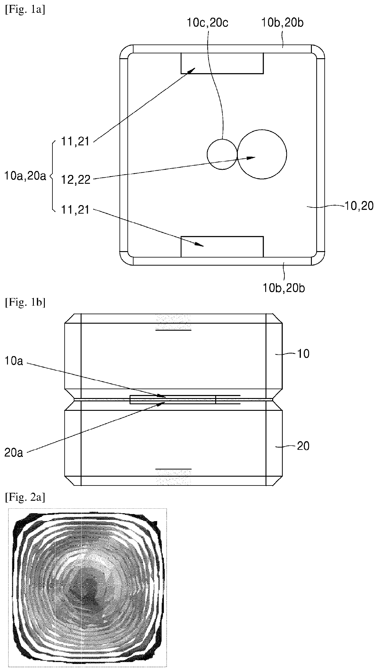
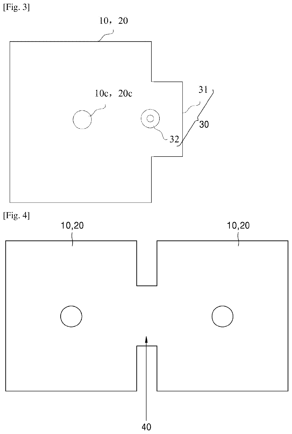
[0042]The disclosure aims to provide a dielectric waveguide filter, and the far-end harmonic suppression of the dielectric waveguide filter and the suppression frequency range are increased by providing coupling structures aiming at high-order modes.

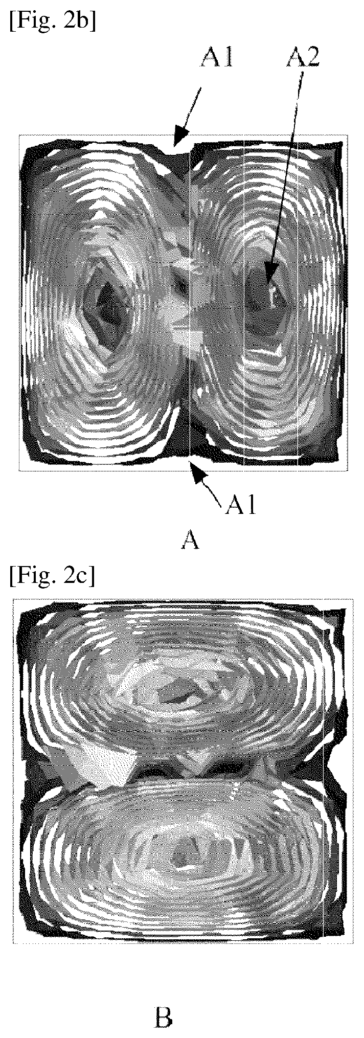
[0043]It should be noted that, each first resonant cavity 10 has its own first high-order mode and second high-order mode, and the first high-order mode and second high-order mode of each first resonant cavity 10 refer to two high-order modes closest to the frequency of its own fundamental mode. Similarly, each second resonant cavity 20 has it...


PUM


Abstract

The disclosure discloses a dielectric waveguide filter, comprising a plurality of first resonant cavities, each two of which are connected to form upper resonant cavities and a plurality of second resonant cavities, each two of which are connected to form lower resonant cavities, wherein the upper resonant cavities and the lower resonant cavities are correspondingly overlapped; each first resonant cavity has a first window coupling structure, wherein the first window coupling structure comprises: at least one of a first window opened at a position where the magnetic field distribution of a high-order mode in the first resonant cavity is the weakest, and a second window opened at a position where the electric field distribution of the high-order mode in the first resonant cavity is the strongest; and each second resonant cavity has a second window coupling structure corresponding to the first window coupling structure.

Description

TECHNICAL FIELD[0001]The disclosure relates to the field of filters, in particular to a dielectric waveguide filter.BACKGROUND ART[0002]With the rapid development of wireless mobile communication technology, the requirements for the far-end out-of-band performance of dielectric waveguide filters have become increasing. However, current dielectric waveguide filters inevitably have a problem of poor suppression and near harmonics in the high-order mode frequency band, usually 1.3 times the frequency. In order to solve the problem, it is usually necessary to use multi-order low-pass filters to suppress high-order modes of the far-end out-of-band, and the additional low-pass filters increase area and insertion loss.[0003]In order to further improve far-end suppression, cascading of a dielectric waveguide filter and a metal cavity may also be adopted. A harmonic of the far-end of the metal cavity is good, cascading of the metal cavity and the dielectric waveguide filter may improve the f...

Claims


Application Information

Patent Timeline
Patent Type & Authority Applications(United States)
IPC IPC(8): H01P1/20H01P1/08
CPCH01P1/2002H01P1/08H01P1/208H01P1/2088
Inventor WANG, RUOMINGKANG, HAIJUZHANG, ZHENKUNNIU, BINGJIAN
Owner SAMSUNG ELECTRONICS CO LTD
Learn More