Circuit module

a technology of circuit modules and core isolators, which is applied in the direction of waveguide devices, basic electric elements, electrical apparatus, etc., can solve the problems of non-reciprocal circuit elements leaking magnetic flux, and achieve the effect of significantly reducing the magnetic coupling between the core isolators and preventing the leakag

Active Publication Date: 2013-09-03
MURATA MFG CO LTD
View PDF15 Cites 0 Cited by
  • Summary
  • Abstract
  • Description
  • Claims
  • Application Information

AI Technical Summary

Benefits of technology

[0007]Preferred embodiments of the present invention provide a circuit module in which multiple isolators (core isolators) having no yokes are mounted to achieve significant reduction and prevention of magnetic coupling between the core isolators.
[0009]According to various preferred embodiments of the present invention, a circuit module in which multiple core isolators having no yokes are mounted enables magnetic coupling between the core isolators to be significantly reduced and prevented.

Problems solved by technology

However, when the yoke is removed from a non-reciprocal circuit element, magnetic flux leaks from around the non-reciprocal circuit element.

Method used


Image

  • Circuit module
  • Circuit module
  • Circuit module

Examples


Embodiment Construction

[0022]A circuit module according to preferred embodiments of the present invention will be described below with reference to the drawings.

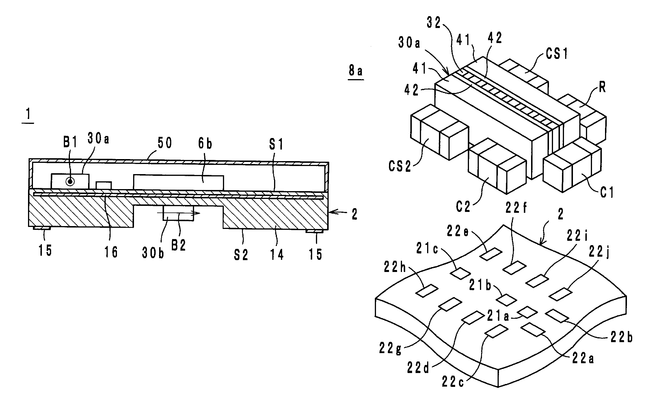
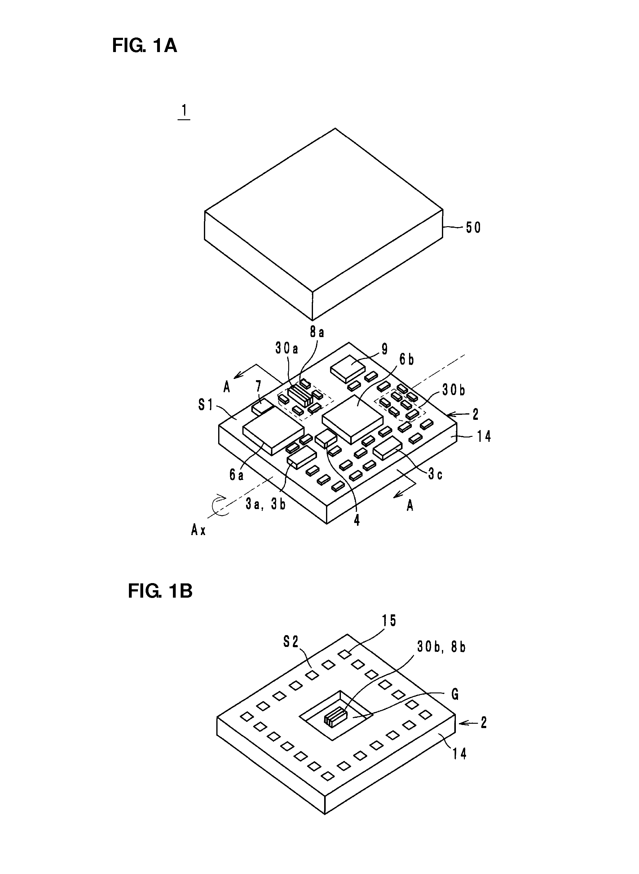
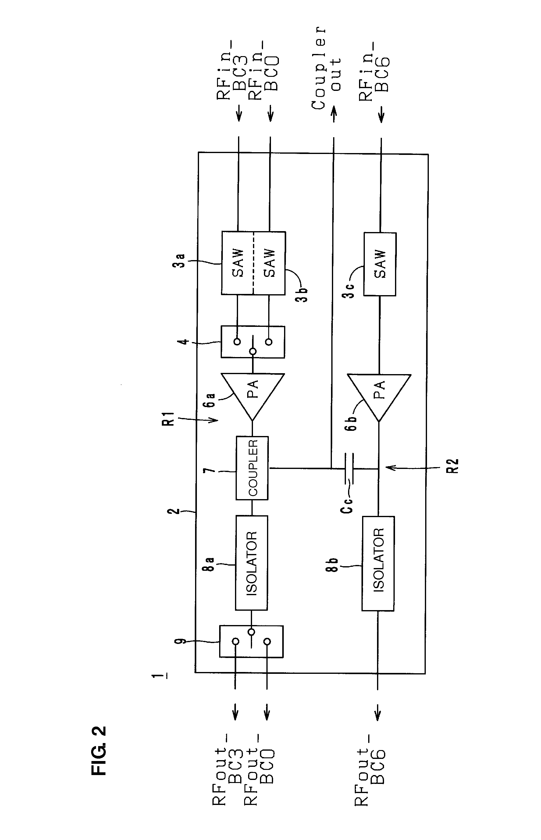
[0023]Now, a configuration of the circuit module will be described with reference to the drawings. FIGS. 1A and 1B includes exploded perspective views of a circuit module 1 according to a preferred embodiment of the present invention. FIG. 1A is an exploded perspective view of the circuit module 1 viewed from the upper side. FIG. 1B is an exploded perspective view of the circuit module 1 rotated by 180° around the axis Ax. FIG. 2 is a block diagram of the circuit module 1 in FIGS. 1A and 1B. FIG. 3 is a sectional structure view taken along the line A-A of the circuit module 1 in FIGS. 1A and 1B. In FIGS. 1A and 1B, only main electronic components are illustrated, and small electronic components, such as a chip capacitor and a chip inductor, are omitted.

[0024]The circuit module 1 constitutes a portion of a transmission circuit of a wireless communi...


PUM


Abstract

A circuit module having reduced magnetic coupling between core isolators. A substrate body includes principal surfaces. A core isolator includes a ferrite, a permanent magnet that applies a DC magnetic field to the ferrite, a first center electrode provided for the ferrite and including one end connected to an input port and another end connected to an output port, and a second center electrode provided for the ferrite so as to intersect the first center electrode insulated from the second center electrode and that includes one end connected to the output port and another end connected to a ground port. The core isolator also includes no yokes preventing leakage of the DC magnetic field to the outside. The core isolators are mounted on the respective principal surfaces such that directions of the DC magnetic fields are parallel or substantially parallel to the principal surface.

Description

BACKGROUND OF THE INVENTION[0001]1. Field of the Invention[0002]The present invention relates to circuit modules, and more particularly to a circuit module including multiple core isolators.[0003]2. Description of the Related Art[0004]A known isolator is, for example, a non-reciprocal circuit element described in Japanese Unexamined Patent Application Publication No. 2006-311455. This non-reciprocal circuit element includes a ferrite having a pair of principal surfaces that oppose each other, multiple center electrodes, permanent magnets having principal surfaces that oppose the principal surfaces of the ferrite, and a circuit board. The multiple center electrodes are formed of a conductor film on the principal surfaces of the permanent magnets so as to intersect each other and be insulated from each other. The center electrodes are also electrically connected to each other via intermediate electrodes formed on edge surfaces that are orthogonal to the principal surfaces of the ferri...

Claims


Application Information

Patent Timeline
Patent Type & Authority Patents(United States)
IPC IPC(8): H01P1/36
CPCH01P1/36
Inventor FURUTANI, KOJI
Owner MURATA MFG CO LTD
Why Eureka
Try Eureka