Coil device with predetermined gap arrangement
a gap arrangement and coil technology, applied in the direction of transformer/inductance details, inductances with magnetic cores, inductances, etc., can solve the problem of deteriorating the magnetic characteristics of each coil
- Summary
- Abstract
- Description
- Claims
- Application Information
AI Technical Summary
Benefits of technology
Problems solved by technology
Method used
Image
Examples
first embodiment
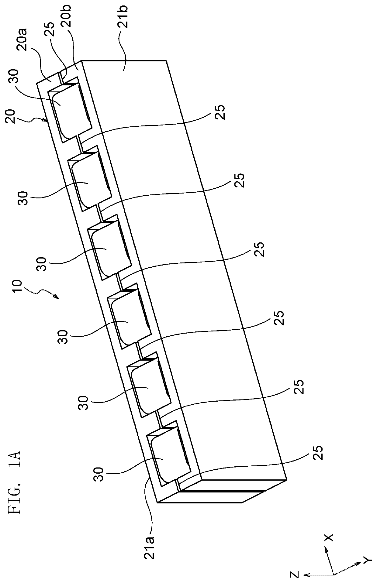
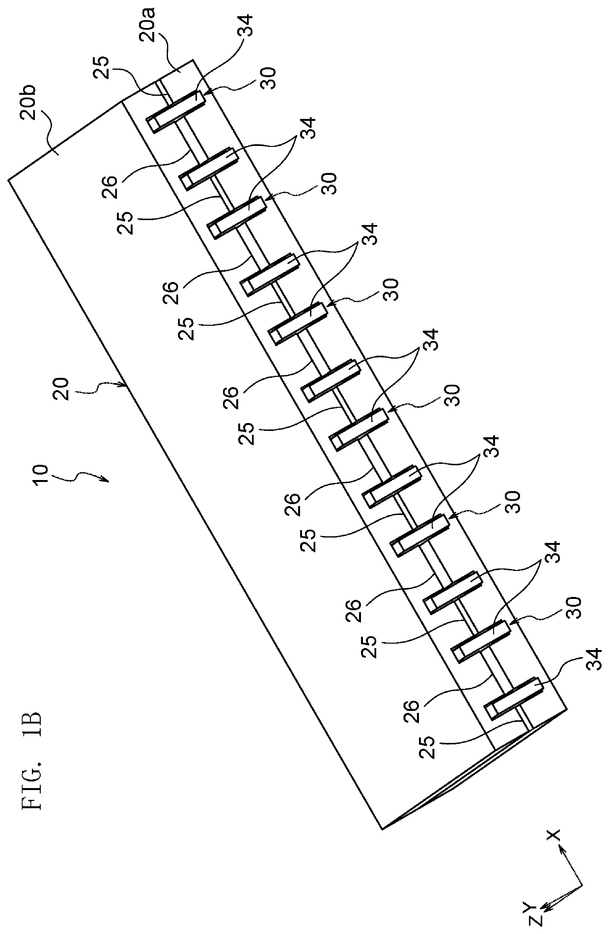
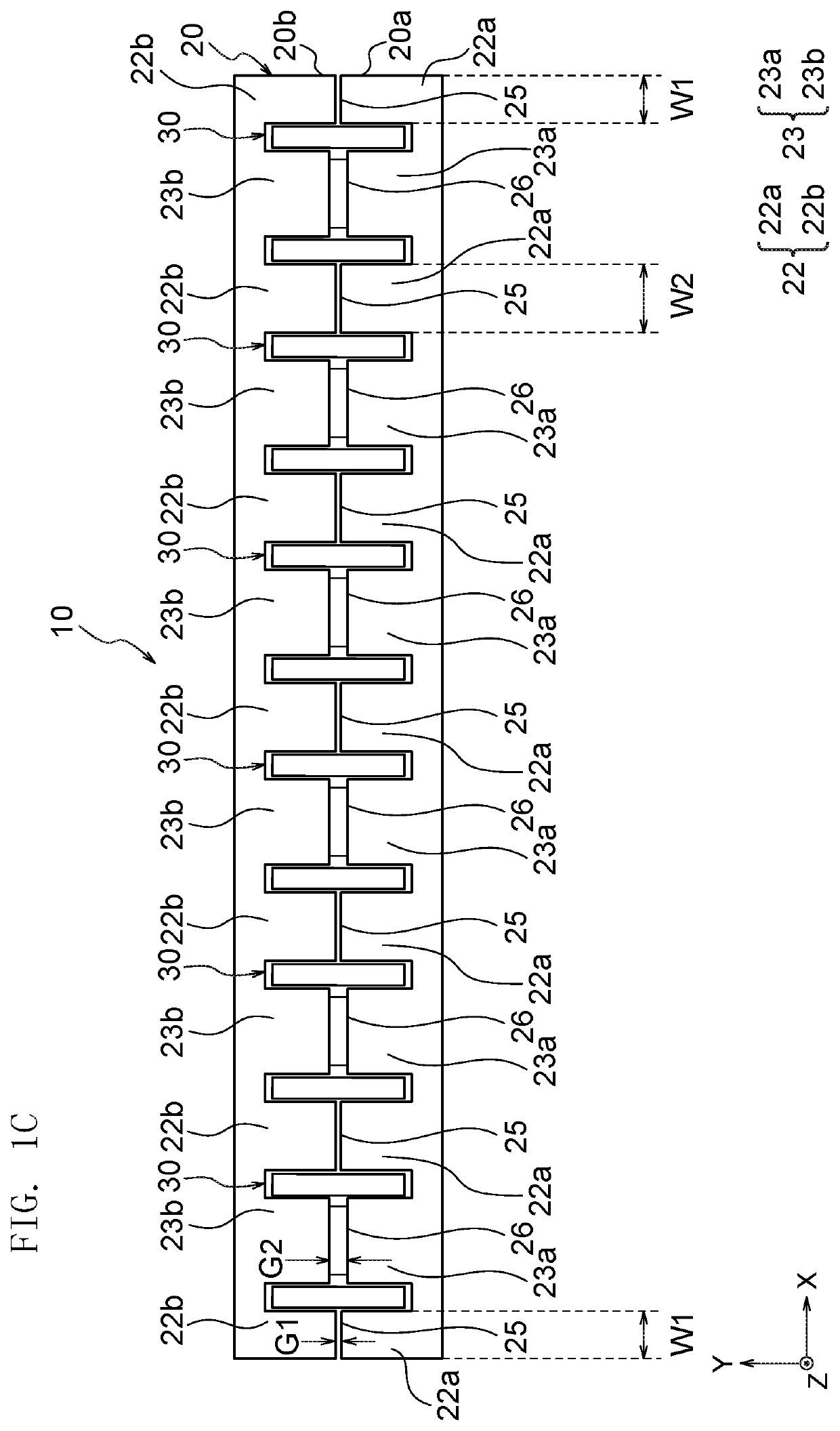
[0042]As shown in FIG. 1A, a coil device 10 includes a core 20 having a substantially rectangular parallelepiped outer shape and a plurality of coils 30 (six coils in the illustrated example) arranged in the core 20. The coil device 10 is, for example, an inductor and has an array structure where the multiple coils 30 are arrayed in the X-axis direction. The coil device 10 has any size. For example, the coil device 10 can have a length of 3-20 mm in each axis direction.
[0043]As shown in FIG. 3A, each of the coils 30 is made from a substantially U-shaped conductor plate. For example, the coils 30 are made from a metal good conductor of copper, copper alloy, silver, nickel, etc., but may be made from any other conductor material. For example, the coils 30 are formed by machining a metal plate, but may be formed by any other method. In the illustrated example, each of the coils 30 is shorter in the Y-axis direction than in the X-axis direction and in the Z-axis direction.
[0044]Each of ...
second embodiment
[0082]Except for the following matters, a coil device 110 according to Second Embodiment of the present invention is similar to the coil device 10 according to First Embodiment and demonstrates similar effects. Their overlapping matters are not explained. In the figures, common members are provided with common references.
[0083]As shown in FIG. 5A, the coil device 110 includes a core 120 and a plurality of coils 130 (three coils in the present embodiment). The core 120 is formed from a first core 120a and a second core 120b and is structured by combining the first core 120a and the second core 120b. The first core 120a is different from the first core 20a according to First Embodiment (see FIG. 2B) in that the first core 120a has notches 127 as shown in FIG. 6. Incidentally, the shape of the second core 120b is similar to that of the first core 120a, and the second core 120b is not thereby explained hereinafter.
[0084]In FIG. 2B, each of the notches 127 is formed by cutting off the lo...
third embodiment
[0094]Except for the following matters, a coil device 210 according to Third Embodiment of the present invention is similar to the coil device 10 according to First Embodiment and demonstrates similar effects. Their overlapping matters are not explained. In the figures, common members are provided with common references.
[0095]As shown in FIG. 8, the coil device 210 includes a plurality of coils 230 (three coils in the present embodiment). As shown in FIG. 9A, each of the coils 230 has mountable parts 234, and the mountable parts 234 are different from the mountable parts 34 according to First Embodiment in that each of the mountable parts 234 has a bending part 341.
[0096]The bending part 341 owned by the mountable part 234 of the first lateral surface part 31 has a shape where the lower end of the first lateral surface part 31 is bent at a substantially right angle from the Z-axis direction to the X-axis direction. The bending part 341 owned by the mountable part 234 of the second l...
PUM
| Property | Measurement | Unit |
|---|---|---|
| length | aaaaa | aaaaa |
| distance | aaaaa | aaaaa |
| width | aaaaa | aaaaa |
Abstract
Description
Claims
Application Information
 - R&D
- Intellectual Property
- Life Sciences
- Materials
- Tech Scout
- Unparalleled Data Quality
- Higher Quality Content
- 60% Fewer Hallucinations
Browse by: Latest US Patents, China's latest patents, Technical Efficacy Thesaurus, Application Domain, Technology Topic, Popular Technical Reports.
© 2025 PatSnap. All rights reserved.Legal|Privacy policy|Modern Slavery Act Transparency Statement|Sitemap|About US| Contact US: help@patsnap.com


