
Drainage system

Active Publication Date: 2018-02-01
ELFBLEND
View PDF4 Cites 5 Cited by
  • Summary
  • Abstract
  • Description
  • Claims
  • Application Information

AI Technical Summary

Benefits of technology

The patent text describes a device for adjusting the height of a conduit, such as a drainage pipe, that can be nested within another conduit to prevent debris from entering. The device includes a rim with reinforcing structures and a removable closure that seals the drainage opening and prevents the ingress of dirt and debris. The closure can be easily removed after installation. The method also includes steps for adjusting the height of the rim until it coincides with a desired floor level and sealing the inlet for liquid to prevent the ingress of debris. The device can be nested and removed after installation. The technical effect of this invention is to provide a convenient and efficient means to adjust the height of a conduit while preventing debris from entering.

Problems solved by technology

The drainage system described therein does not, however, comply with the building code in the United States.
The present inventor has found that such screw thread drainage systems are tedious to install.

Method used


Image

  • Drainage system
  • Drainage system
  • Drainage system

Examples


first embodiment

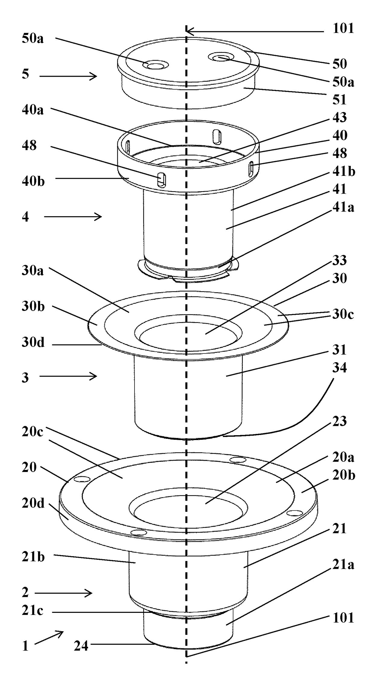
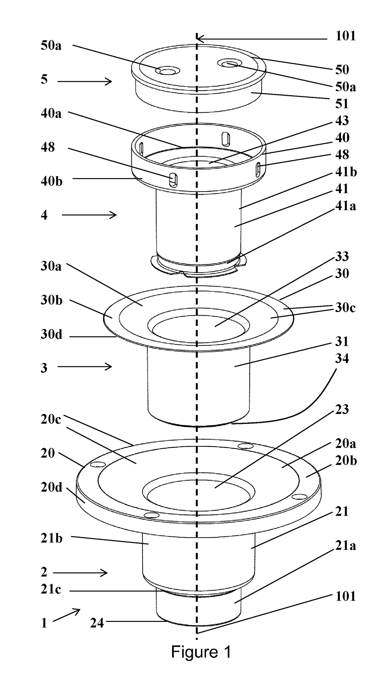
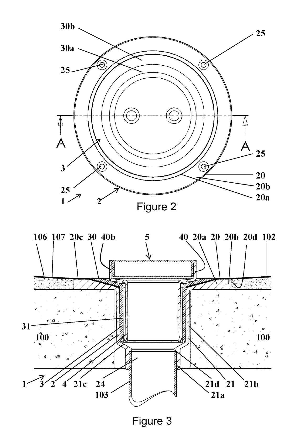
[0200]Referring first to FIGS. 1 to 7, there is shown a drainage system 1 for installation within a concrete or timber subfloor 100 (as seen in FIGS. 3 and 15). The drainage system 1 includes an outer drainage conduit 2 (3 inch×2 inch), an inner drainage conduit 3, a height adjustable conduit 4 and a closure 5. A central axis 101 is shown in exploded view FIG. 1 extending through the outer drainage conduit 2 (3 inch), inner drainage conduit 3, height adjustable conduit 4 (4 inch×3 inch) and removable closure 5 (4 inch).

[0201]The outer drainage conduit 2 includes a rim 20 which is adapted to be secured to an upper surface 102 of the subfloor 100. The rim 20 includes an inlet for liquid 23 and extends substantially laterally relative to the central axis 101. The outer drainage conduit 2 also includes a pipe body 21 extending from the rim 20 and is adapted to be connected to a waste pipe riser 103 (see FIG. 3) which extends beneath the subfloor 100. If a wooden subfloor 100, the pipe b...

second embodiment

[0237]Referring now to FIGS. 10 to 13, there is shown a drainage system 7 for installation within a concrete or timber subfloor 100. The drainage system 7 includes an outer drainage conduit 8, a height adjustable conduit 4a and a closure / cap 5a. The height adjustable conduit 4a and enclosure / cap 5a are substantially identical to the height adjustable conduit 4 and closure / cap 5. A central axis 101 is shown in exploded view FIG. 10 extending through the outer drainage conduit 8, height adjustable conduit 4a and cap 5a.

[0238]The outer drainage conduit 8 includes a rim 80 which is adapted to be secured to an upper surface 102 of the subfloor 100. The rim 80 includes an inlet for liquid 83 and extends substantially laterally relative to the central axis 101. The outer drainage conduit 8 also includes a pipe body 81 extending from the rim 80 and is adapted to be connected to a waste pipe riser 103 (see FIG. 12) which extends beneath the subfloor 100. The pipe body 81 includes an outlet ...


PUM


Abstract

A drainage system (1) for installation in a wet area such as a shower stall. The drainage system (1) comprises an outer drainage conduit (2) adapted to extend within a subfloor (100) of a wet area and an inner drainage conduit (3). The conduit (2) comprises a rim (20) and a pipe body (21). The inner drainage conduit (3) also comprises a rim (30) and a pipe body (31). The rim (30) and pipe body (31) are nestable within the outer drainage conduit (2). When nested, the pipe bodies (21, 31) are adapted to be connectively sealed together using sealant, the rims (20, 30) are adapted to hold a waterproofing membrane (107) between the rims (20, 30,) and to be connectively sealed in a water-tight manner to the waterproofing membrane (107) using sealant or, in the absence of a waterproofing membrane (107), the rims (20, 30) are adapted to be connectively sealed together using sealant in a water-tight manner.

Description

FIELD OF THE INVENTION[0001]This invention relates to a drainage system. In particular, the invention relates to a drainage system and method of installation, for providing drainage in a wet area such as a shower stall.BACKGROUND OF THE INVENTION[0002]Many different types of drainage systems for providing drainage in wet areas such as bathrooms, laundries and shower stalls have been proposed. One such drainage system is described in U.S. Pat. No. 6,799,606 B1. The drainage system described therein does not, however, comply with the building code in the United States.[0003]Drainage systems commonly used in the United States have drainage conduits or pipes that are threaded and required to be screwed together for installation, or need to be adjusted in height by screwing one or more components relative to one another along screw threads. The present inventor has found that such screw thread drainage systems are tedious to install.SUMMARY OF THE INVENTION[0004]One or more embodiments o...

Claims


Application Information

Patent Timeline
IPC IPC(8): E03F5/04
CPCE03F5/0408
Inventor HOWSON, LESLIE LAWRENCE
Owner ELFBLEND
Learn More