Image forming apparatus
- Summary
- Abstract
- Description
- Claims
- Application Information
AI Technical Summary
Benefits of technology
Problems solved by technology
Method used
Image

Examples
modified example 1
[0352]Specifically, for example, in the first embodiment, the correction amount VR is determined based on the temperature difference coefficient C1, in the second embodiment, the correction amount VR is determined based on the temperature difference coefficient C1 and the frequency coefficient C2, and in the third embodiment, the correction amount VR is determined based on the temperature difference coefficient C1, the frequency coefficient C2, and the print rate coefficient C3.
[0353]However, the correction amount VR may be determined based on the temperature difference coefficient C1 and the print rate coefficient C3. In this case, for example, as shown in FIG. 21 corresponding to FIGS. 4 and 17, the image forming apparatus is provided with, as major constituent elements related to the correction operation of the potential difference ΔV, the temperature difference calculation part 98, the temperature difference coefficient determination part 99, the correction amount determination ...
modified example 2
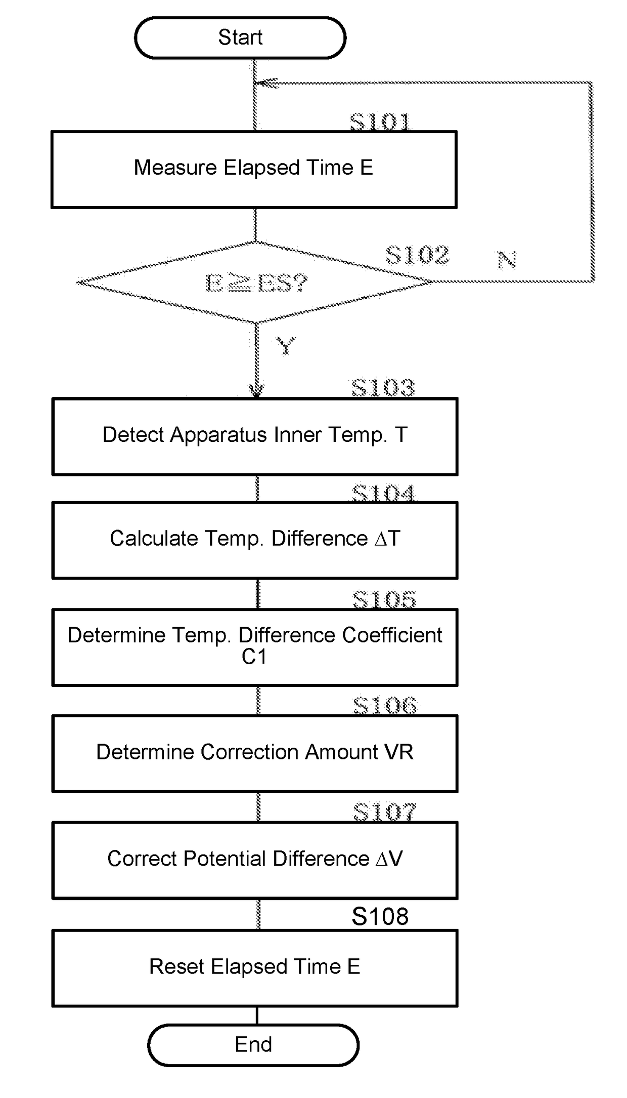
[0358]Further, for example, in the first to third embodiments, using the time measure part 96 and the time judgment part 97, when the elapsed time E has reached the target time ES, the correction operation of the potential difference ΔV by the potential difference correction part 101 is performed.
[0359]Further, without using the time measure part 96 and the time judgment part 97, regardless of the elapsed time E, the correction operation of the potential difference ΔV by the potential difference correction part 101 is performed. Also in this case, since the correction accuracy, etc., of the potential difference ΔV is improved, the same effect can be obtained.
[0360]However, as described above, in order to reduce the frequency that the correction operation of the potential difference ΔV is performed, it is preferable to perform a correction operation of a potential difference ΔV by the potential difference correction part 101 while judging whether or not the elapsed time E has reached...
modified example 3
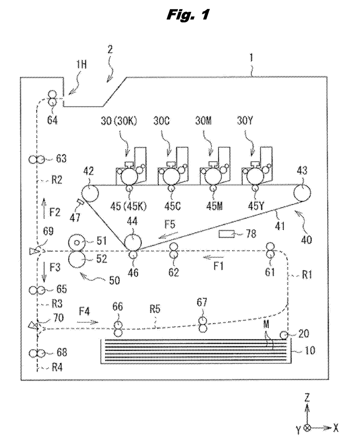
[0361]Further, for example, in the first to third embodiments, the temperature of the transfer part 40 (intermediate transfer belt 41) is measured as the apparatus inner temperature T. However, the installation location of the temperature sensor 78 can be arbitrarily changed.
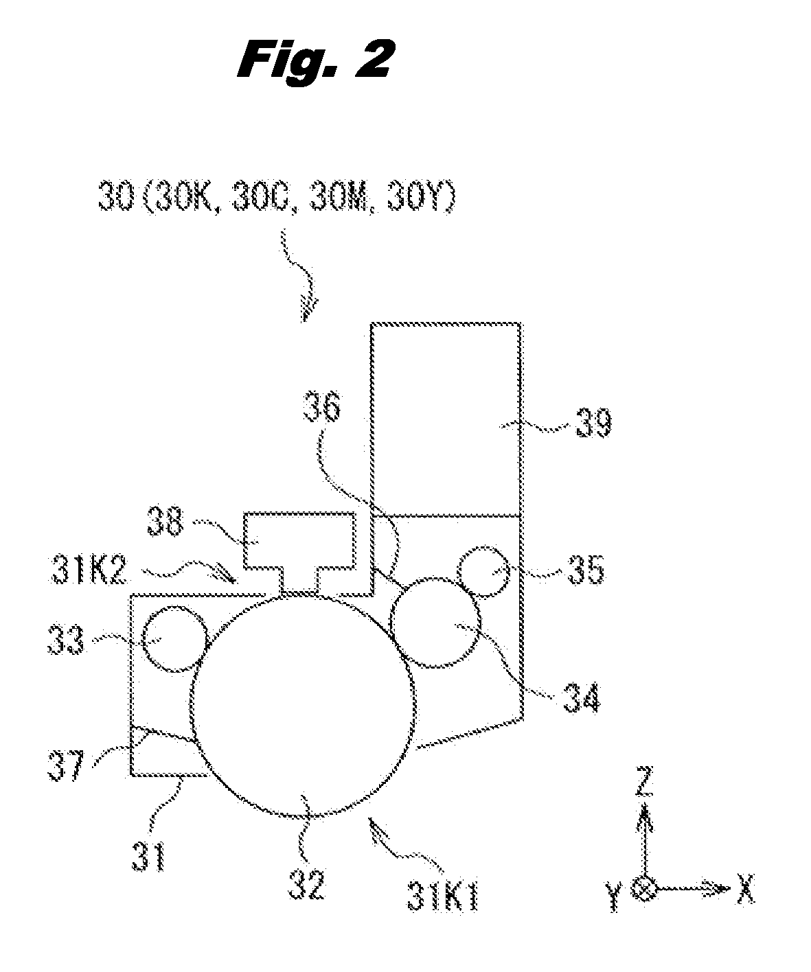
[0362]Specifically, for example, as shown in FIGS. 23 to 26 corresponding to FIG. 2, the installation location of the temperature sensor 78 may be changed. In this case, for example, as shown in FIG. 23, by setting a temperature sensor 78 in the vicinity of the photosensitive drum 32, the temperature of the photosensitive drum 32 may be detected as the apparatus inner temperature T. For example, as shown in FIG. 24, by setting the temperature sensor 78 in the vicinity of the development roller 34, the temperature of the development roller 34 may be detected as the apparatus inner temperature T. For example, as shown in FIG. 25, by setting the temperature sensor 78 in the vicinity of the development roller 34, th...
PUM
 Abstract
Description
Claims
Application Information
 - Generate Ideas
- Intellectual Property
- Life Sciences
- Materials
- Tech Scout
- Unparalleled Data Quality
- Higher Quality Content
- 60% Fewer Hallucinations
Browse by: Latest US Patents, China's latest patents, Technical Efficacy Thesaurus, Application Domain, Technology Topic, Popular Technical Reports.
© 2025 PatSnap. All rights reserved.Legal|Privacy policy|Modern Slavery Act Transparency Statement|Sitemap|About US| Contact US: help@patsnap.com